What parameters impact the EVM of transmitter chain ?
The error vector magnitude or EVM is a measure used to quantify the performance of a digital radio transmitter or receiver. A signal sent by an ideal transmitter or received by a receiver would have all constellation points precisely at the ideal locations, however various imperfections in the implementation (such as carrier leakage, low image rejection ratio, phase noise etc.) cause the actual constellation points to deviate from the ideal locations. Informally, EVM is a measure of how far the points are from the ideal locations.
Definition:
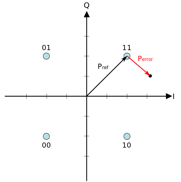
An error vector is a vector in the I-Q plane between the ideal constellation point and the point received by the receiver. In other words, it is the difference between actual received symbols and ideal symbols. The average amplitude of the error vector, normalized to peak signal amplitude, is the EVM.
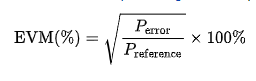
where Perror is the RMS amplitude of the error vector.

Preference is usually defined by the RMS power of the reference signal constellation (this is valid for both Single and Multicarrier modulations
EVM is defined as a percentage in a compatible way:
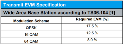
3GPP EVM Specs
3GPP defines EVM specification for LTE eNodB transmitter chain as shown below:
Factors Affecting EVM
Local Oscillator Phase Noise
The phase noise of an oscillator or PLL is typically specified in the frequency domain. Random phase fluctuations of an ideal sine wave signal in the time domain translate into a spectral component f0 with noise side bands in the frequency domain.

where σ is the rms LO phase noise.
Simulation example of Phase noise when rms phase jitter of 10 degrees:

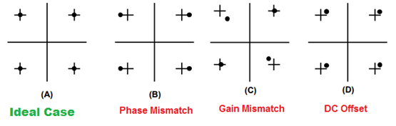
DC Offset, and Gain and Phase Mismatch
On the other hand, DC offset, and gain and phase mismatches in the in-phase and quadrature IQ signal paths will directly affect modulation accuracy. These impairments can be seen as LO leakage and unwanted sideband rejection performance. As far as the constellation is concerned, for BPSK pilot symbols in particular, an IQ gain mismatch results in pilot symbols spread mostly along the I-axis, while a phase mismatch would result in the pilot symbols spread along the Q-axis. Most transceivers and vector modulators specify these impairments as LO leakage and single sideband rejection in decibels, dB.
Following figure shows how IQ Mismatches impacts the EVM Constellation:
Nonlinearities
As the transmitter operates near the 1 dB compression point, there is third order intermodulation nonlinearities impact on the EVM. So better is the IIP3 of the device, better is the EVM.
Following is one example which shows how EVM degrades when OFDM signal is fed to a non-linear device having IIP3 of +10dBm.
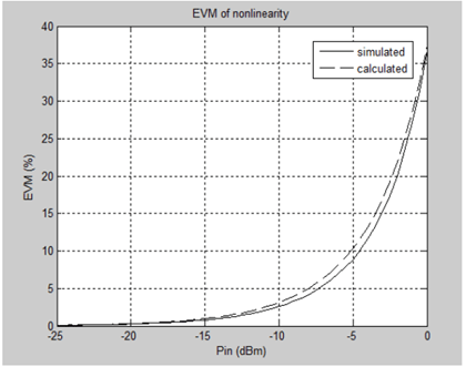
So better is the IIP3 of the device, better is the EVM.