5G NR BWP Types and BWP Operations
In 5G New Radio the cell bandwidth is expected to be large compared to LTE, but a UE’s receive and transmit bandwidth is not necessarily required to be same as of cell bandwidth. As per 3GPP specification 38.300, the receive and transmit bandwidth of a UE can be adjusted to a subset of total cell bandwidth referred as BWP. This bandwidth can shrink during period of low activity to save power; the bandwidth location can be changed to allow different services. The bandwidth adaption can be achieved by configuring the UE with BWP(s) telling the UE which of the configured BWPs is currently the active one.
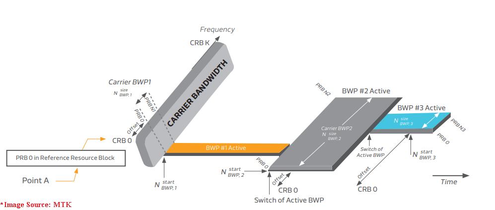
3GPP 38.211 specifies Bandwidth Parts (BWP) as a contiguous set of physical resource blocks, selected from a contiguous subset of the common resource blocks for a given numerology (µ) on a given carrier. To know basics about Bandwidth part please read our following post.
BWP Allocation Types
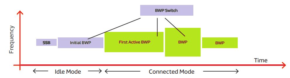
Figure below represents the different BWPs types available for a UE. Considering typical use cases, Idle Mode BWP is smaller than Connected Mode BWPs.
Three types of BWP are available:
- Initial BWP
- Active BWP (UE Specific)
- Default BWP (UE Specific)
Initial BWP is used to performs Initial Access Process. It includes Parameters like RMSI (Requested Minimum System Information), CORESET* and RMSI Frequency location/bandwidth/SCS. It can be 24~96 PRBs with different settings and relaxed to wider BWP after RMSI decoding.
Active BWP is defined as UE specfic can also be used to BWP performs Initial Access Process. It is the first BWP where UE starts data transfer after RRC configuration/reconfiguration. The very first Active BWP should be different from the default BWP.
Default BWP is again UE specific BWP and configured during RRC reconfiguration, if it not configured then it can be assumed that Intial BWP is the default BWP. Every UE would switch back to default BWP when BWP timer expires.
Bandwidth Parts Operations during Initial Access
The BWP parameters are used to configure the mobile operator between the UE and the cell. According to 3GPP TS
38.331 for each serving cell the network configures at least an initial bandwidth part, comprising of downlink
bandwidth part and one (if the serving cell is configured with an uplink) or two (if using supplementary uplink
– SUL) uplink bandwidth parts. Furthermore, the network may configure additional uplink and downlink
bandwidth parts.
The bandwidth part configuration is split into uplink and downlink parameters as well as into common and
dedicated parameters. Common parameters (in BWP-UplinkCommon and BWP-DownlinkCommon) are “cell
specific” and the network ensures the necessary alignment with corresponding parameters of other UEs. The
common parameters of the initial bandwidth part of the PCell are also provided via system information. For all
other serving cells, the network provides the common parameters via dedicated signaling.
| Step | Stage | DL BWP | UL BWP | Processing |
|---|---|---|---|---|
| 0 | PSS and SSS Decode | DL Synchronization | ||
| 1 | MIB decode | UE decode MIB and get CORESET #0 configuration |
||
| 2 | RMSI decode | CORESET #0 | Get Initial DL-BWP and Initial UL-BWP setting for RMSI decoding | |
| 3 | Msg-1-UE >——> gNB | Initial UL-BWP | Random Access Request to gNB | |
| 4 | Msg-2-UE <—–< gNB | CORESET #0 | Random Access Response (RAR) gNB | |
| 5 | Msg-3-UE >——> gNB | Initial UL-BWP | RRC connection request | |
| 6 | Msg-4-UE <—–< gNB | CORESET #0 | RRC connection setup Configure UE specific BWP (default/1st active/ other) BWP If not configured, still use initial BWP |
|
| 7 | Msg-5-UE >——> gNB | 1st Active BWP | 1st Active BWP | RRC set-up completed Initial BWP is the 1st Active BWP if no additional configuration carried in Msg4 |
BWP Activation/Deactivation and Switching
The traffic patterns within one active data session can change frequently as the data rate may increase or decrease based on the type of service or the user behavior (accessing the internet and answering a phone call for example). It becomes very important to quick switch between different bandwidth parts to manage different power consumption for different data rates.
According to TS 38.321 BWP selection and switching can be done with different mechanisms as listed below:
- RRC-Based Adaptation: It is more suitable for semi-static cases since the processing of RRC messages requires extra time, letting the latency reach ~10 msec. Due to longer switching latency and signaling overhead, a RRC-based method can be used for configuring a BWP set at any stage of the call, or for slow adaptation type services (e.g., voice) where the resource allocation is not changing rapidly within the same data session.
- MAC CE (Control element):It is used upon initiation of Random Access procedure
- DCI-Based Adaptation: It is based on PDCCH channel where a specific BWP can be activated by BWP indicator in DCI Format 0_1 (UL Grant) and Format 1-1 (DL scheduling). This method better fits on-thefly BWP switching as using this method the latency is as low as 2 msec. However, this method requires additional considerations for error handling as UE may fail to decode the DCI with BWP activation/deactivation command.
- Timer-Based implicit fallback to default BWP is a mechanism designed to mitigate possible DCI errors. If the UE is not explicitly scheduled with a BWP after the timer expires, it will automatically switch to the default BWP.
Reference: White Paper from MediaTek Bandwidth Part Adaptation
Related Post:
- 5G NR Grant Free Dynamic Scheduling
- 5G NR sounding Reference Signal (SRS)
- 5G NR RACH Preamble Types: Long and Short Preambles
- NR-Logical Channels,Transport Channels and Physical Channels Mapping
- NR Radio Network Temporary Identifier (RNTI)
- 5G New Radio Throughput Capabilities


