5G NR RLC – AM Mode Data Transmission
In 5G NR, RLC has 3 different modes of operations TM, UM and AM and each of the mode can transmit and receive data, serving different logical channels as per their requirement. This post provides an overview of AM Mode data transmission.
RLC AM Mode Characteristics
- Buffering done both at Transmission and Reception
- Segmentation done at TX and Reassembly at RX
- Feedback mechanism is required ACK/NACK for RLC PDU
- Data for SRB1/SRB2/SRB3 and DRBs use RLC AM Mode
- SN Size AM (12,18) bits
- RLC AM mode Complete/Segmented SDU is associated with SN
- 1 RLC SDU = 1 RLC PDU
How Data Transfer happens through RLC ?
RLC entity receives/sends PDCP PDUs (i.e. RLC SDUs) from/to PDCP layer and sends/receives RLC PDUs to/from its peer RLC entity via MAC & PHY layers.
- PDU is output of a layer
- SDU is input to a layer

What is PDU Transmission Order ?
In, RLC AM mode following order is considered for PDU transmission.
- Control PDU (RLC Status PDU)
- Retransmit PDU
- Segmented PDU
- Complete PDU
RLC Transmission (Complete/Segmented PDU)
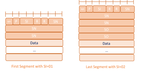
The figure below depicts the transmission of complete and Segmented PDUs.

The number of RLC PDU(s) are transmitted according to the MAC TB size. If the MAC TB size is not sufficient enough to transmit the Complete RLC PDU, then the RLC PDU is segmented. MAC TB size depends upon the scheduled bytes – which is based on the radio condition.
-
- SI: The SI field indicates whether an RLC PDU contains a complete RLC SDU or the first, middle, last segment of an RLC SDU.
- SO: Segment Offset ( Only for Middle, Last Segment)
RLC AM Data Retransmission
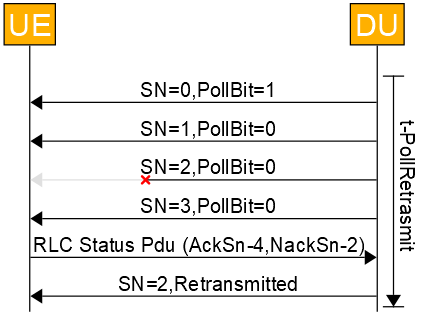
In AM mode, every RLC PDU is sent with sequence number in ascending order and stored in Re-transmission buffer. As RLC AM supports ARQ to ensure reliable delivery, therefore RLC STATUS PDU message is sent by UE to indicate the current status of RLC PDUs received at UE. In Figure below :
- RLC PDU with SN=2 dropped,
- therefore in RLC STATUS PDU (AckSn-4, NackSn-2) sent from UE and
- after receiving the RLC STATUS PDU, RLC PDU with SN=2 is retransmitted from DU.
RLC Max Retransmission
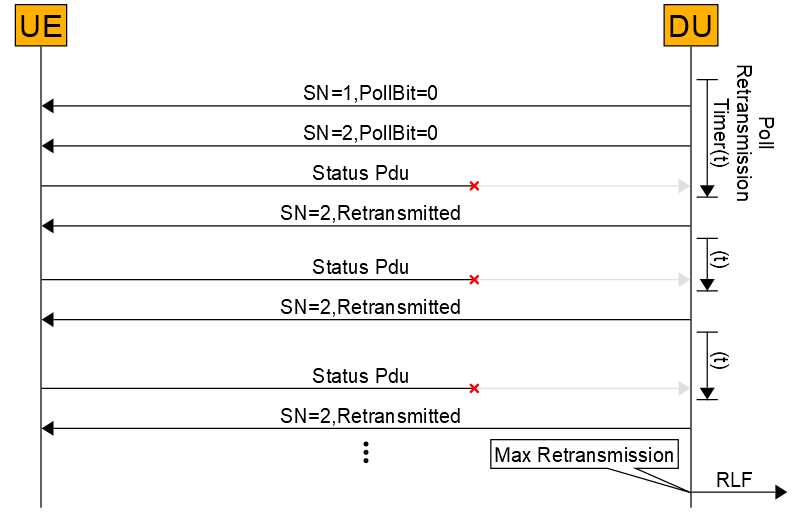
if STATUS PDU is dropped, then post expiry of Poll Retransmission timer, a RLC PDU with SN=2 is retransmitted – which is latest RLC PDU that is transmitted from DU. If the Poll Retransmit timer expiry count exceed the maxRetxThreshhold value then RLF (Radio Link Failure) is triggered and the UE is released.
RLC Window Stall
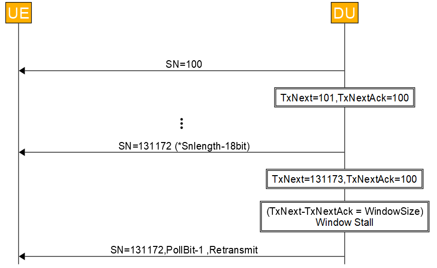
RLC Window Stall happens when difference between TxNext & TxNextAck is equal to SN Window Size ( half of Max SN Size). In Figure below, Window Stall has happened and if there is no RLC PDU in the Retx Buffer then Highest Transmitted PDU (Sn-131172) is retransmitted.
-
-
- TxNext: This state variable holds the value of the SN to be assigned for the next newly generated AMD PDU
- TxNextAck: This state variable holds the value of the SN of the next RLC SDU for which a positive acknowledgment is to be received in-sequence, and it serves as the lower edge of the transmitting window.
-
In case of Window Stall, unsolicited request is sent to PDCP in CU to stop sending the data. As per the Specs, Stall condition happens when no ACK is received for the transmitted PDU count (WINDOW_SIZE =13072), it mean DU has to maintain 131072 buffers.
Issue with WindowStall condition to WindowSize
- This huge buffers may not be supported by DU due to system limitation.
- It may be possible that spurious UE consume all the buffers leaving no buffers for other UEs.
Therefore Window stall condition threshold can be modified according to this formula
- Window Stall Threshhold = (MAX_DATA_RATE/AVG_PDU_SIZE)*RLC_RTT
- RLC_RTT = Status Prohibit Timer + MAX_HARQ_RETX
Here
-
- MAX_DATA_RATE: Maximum Data Rate Supported by UE
- RLC_RTT: RLC Round Trip Time
- MAX_HARQ_RETX: Maximum Harq Retransmission
- AVG_PDU_SIZE: Average RLC PDU Size
RLC AM PDU Receive and Reassembly
- The AMD PDU is received from the MAC layer.
- The RLC layer proceeds if RLC PDU SN is within the receive window, if not, then the packet is dropped
- The RLC layer also checks if the AMD PDU carried the RLC SDU segment bytes that have already been received (checks for duplication). It moves ahead with the processing as the received AMD PDU contains new data bytes.
- The RLC layer places the AMD PDU in the reception buffer
Status Report is sent periodically to share the reception status of UL packets to the UE. Next two figure below depicts the updation of RLC UL State Variable according to the processing done for the RLC packets in t-reassembly (t1,t2,t3) timer. It is assumed that in each t-reassembly, 50 RLC PDUs are received and in each t-reassembly timer duration STATUS PDU is sent. RLC SN Reception missed as TB (MAC Transport Block) not received from UE.

In Figure below, MAC TB with RLC SN(5~8) are lost during t1 time and is received during t2 due to HARQ Retransmission. Here as seen, STATUS PDU sent in t2 duration does not includes again the AckSn=5.
- Note: Packet Lost in t1 duration will be informed always in t3 duration to UE using STATUS PDU (using NackSn).
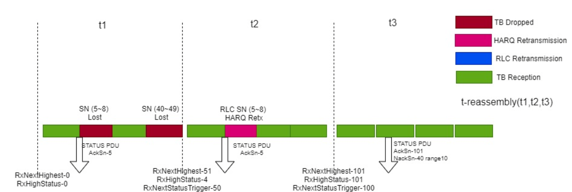
In Figure 16 , MAC TBs with RLC SN(5~8) and RLC SN(40~49) is lost in t1 duration. In t2, Status PDU is sent before the reception of Harq Retx (Harq Retransmitted TB) with RLC SN(5~8), therefore STATUS PDU does not report the reception of RLC SN(5~8) and only send STATUS PDU(AckSn-5). Post t2 expiry, it is assumed that MAC TB with RLC SN(40~49) is lost and lost packet information is sent to UE in STATUS PDU( AckSn-50, NackSn-40, range-10).
RLC packets lost in t1 are reported to UE in STATUS Report during t3. In STATUS PDU (AckSn 50, NackSn-40, range10). PDUs from SN (40 – 49) are considered to be lost or dropped.
- Note: Reassembly timer is the duration during which the DU-RLC waits for HARQ Retransmission from UE for the lost RLC packets.
Receive and Reassembly RLC Timers
- tReassembly: tReassembly >= time for DL packet to reach UE + time for HARQ Out
- tpollretransmit: tpollretransmit >= tstatusProhibit + 2 PUSCH transmission ( BSR + RLC Status PDU)
- tstatusProhibit: HARQ RTT <= tstatusProhibit <= tReassembly
Article Submitted By:

Prerit Jain has about 15 years of experience in 4G, 5G System development and currently working as Sr. Member of Technical Staff, Altiostar Networks Inc. He completed his Bachelors of Technology from NSIT, Delhi. from India.

Mangala Jaji has about 15 years of experience in 4G, 5G System development and currently working as Architect System-Software Sasken Technologies Ltd, India. She has completed her engineering in computer Science, from Karnatak University, India.


