5G NR Quasi-Colocation Concept, Types and Application
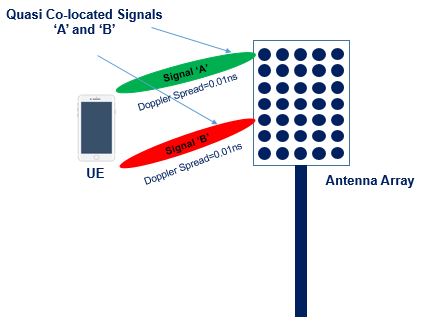
Two signals transmitted from same antenna port shall experience the same radio channel, where as transmitting it from two different antenna ports shall experience different radio conditions. But there can be some cases where transmitting signals from two different antenna ports experience radio channels having common properties. In such cases the antenna ports said to be Quasi-Colocation (QCL).
For example, signal ‘A’ and signal ‘B’ transmitted from Antenna Port#1 and Antenna Port#2 respectively, When processed at receiver it is found the both signal experienced common radio channel properties (Doppler Spread) , then Antenna Port#1 and Antenna Port#2 said to be Quasi-Colocation Antenna Port and signal ‘A’ and ‘B’ said to be Quasi-Colocation Signals.

As per the 3GPP definition for Quasi-Colocation (QCL)
Two antenna ports are said to be quasi co-located if properties of the channel over which a symbol on one antenna port is conveyed can be inferred from the channel over which a symbol on the other antenna port is conveyed
Radio channel properties to make Antenna Ports/ Signal QCL
The radio channel properties which may be common across the antenna ports includes Doppler spread/ shift, average delay, delay spread, average gain and spatial receiver parameters. This properties are known as “large-scale properties “. A short definition of each is given below
-
- Doppler Shift: Doppler shift is a shift in the frequency of the radio signal relative to motion of the receiver. E.g. gNB transmits a radio signal of a frequency “X” however the receiver (UE) is in mobility traveling away from the gNB so that same radio signal due to the distance of the UE by the time it reaches the UE the frequency is changed to “Y” , this phenomenon is known as Doppler shift. A real life example is the sound of a speeding train that comes close and speeds away to person standing on the platform, is called Doppler shift of sound wave.
- Doppler Spread: Doppler Spread is known as fading rate, difference between the signal frequency at the Tx & Rx with respect to time is called Doppler spread. E.g. The rate at which the train sound changes over time is called Doppler spread.
- Average Delay: When signal is transmitted from multiple antenna, it reaches to receiver through multiple path reflect from surrounding clutter. In multi path scenario the average time taken to receive all the Multi path components at the receiver is known as Average Delay.
- Delay Spread: Difference between the time of arrival of the earliest significant multi path component i.e. typically the line of sight (LOS) component and the time of arrival of the last multi path component is known as Delay spread.
- Spatial Receiver Parameter: Spatial Receiver Parameter are refers to Beam Forming properties of Downlink received signal like dominant Angle of Arrival, average Angle of Arrival at UE.
3GPP has introduced Quasi- Colocation (QCL) concept to help the UE with channel estimation, frequency offset error estimation and synchronization procedures. For example, if UE knows that the radio channels corresponding to two different antenna ports is QCL in terms of Doppler shift then UE can determine Doppler shift for one antenna port and then apply the result on both antenna ports for channel estimation. This avoids the UE to calculate doppler for both antenna port separately.
5G NR have support for multi-antenna transmission, beam-forming, and simultaneous transmission from multiple geographically separates sites (CoMP). In such cases, the channels of different antenna ports relevant for a UE may differ even in terms of radio channel properties and QCL antenna port may be geographically separated.
Types of Quasi-Colocation
As per 3GPP specification 38.214 5.1.5, there are following four types of QCL, named as QCL-Type A, QCL-Type B QCL-Type C and QCL-Type D. The four type indicates that which large scale channel properties are common across the sets of antenna ports.
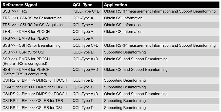
Table below provides each QCL indicating combination of channel properties and application.

QCL Relationship between NR Reference Signals
As per 3GPP specification 38.214 section 5.1.5, based on Tracking Reference Signal (TRS) information, repetition in nzp-CSI-RS-Resource Set & CSI Resource Type (periodic & a periodic) in csi-ResourceConfig, there could be following possible QCL relationships between NR reference signals for both sub 8GHz and mmwave.
- QCL relationship between SSB and DMRS before RRC signaling

- Relationship between Reference Signals for below 8GHz after RRC signalling

- Relationship between Reference Signals for Above 8GHz after RRC signalling

How QCL is Used and sent to UE?
QCL can be used to support reception of both PDSCH and PDCCH at UE. In both cases, the gNB can indicate the antenna port used by a specific SS/PBCH block is QCL with the antenna port used by the PDSCH and PDCCH. Also gNB can indicate that the antenna port used by specific CSI Reference signal is QCL with the antenna port used by PDSCH or PDCCH transmission.
gNB use a combination of RRC signalling, MAC CE signalling and PDCCH to indicate UE about which SS/PBCH or CSI RS are QCL with PDSCH and PDCCH.
- Steps for PDSCH QCL
- Step#1 gNB sends RRC signalling to configure Transmission Configuration Indicator (TCI) for the PDSCH QCL
- Step#2 Send MAC Control Element to activate the TCI state. MAC CE can be used to activate upto 8 TCI states
- Step#3 Send DCI indicating PDSCH resource allocation
- Step#4 UE decodes PDSCH using QCL information provided by TCI state
- Steps for PDCCH QCL
- Step#1 gNB sends RRC signalling to configure Transmission Configuration Indicator (TCI) for the PDCCH QCL
- Step#2 Send MAC Control Element to activate the TCI state. MAC CE can be used to activate one TCI state for a specific CORSET
- Step#3 UE decodes PDCCH using QCL information provided by TCI states
Reference
- 3GPP 38.214, 5G NR, Physical layer procedures for Data
- Article by Naveen Chelikani on LinkedIN
Related Post
- 5G NR Antenna Port – Logical and Physical Antenna Mapping
- 5G NR Physical Layer Timing Unit
- 5G Subcarrier Spacing, Frame and Subframe, Slot and OFDM Symbol
- Motivation Behind Having Multiple Numerology in 5G NR
- 5G NR Resource Block Definition and RB calculations
- 5G NR Modulation and Coding Scheme (MCS)


