


The latency performance of a communication system is analyzed for both control plane and user plane. In this post lets discuss about control plane latency.
The definition of control plane latency as per 3GPP TR 38.913 is “the time to move from a battery efficient state e.g. IDLE to the start of continuous data transfer e.g. ACTIVE” . Considering agreements made during the study item phase of NR, the control plane latency can be analyzed as the transition time from an inactive state to the time to send the first uplink packet in the inactive state.
As detailed signaling procedures are not available for connection resumption, let take LTE resume call flow as reference call setup procedure for control plane latency shown below.
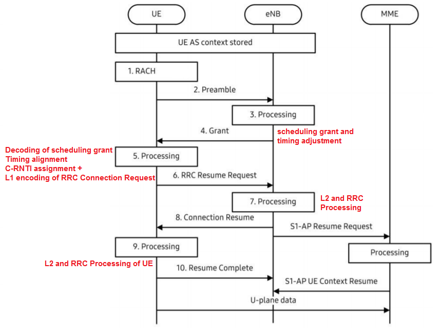

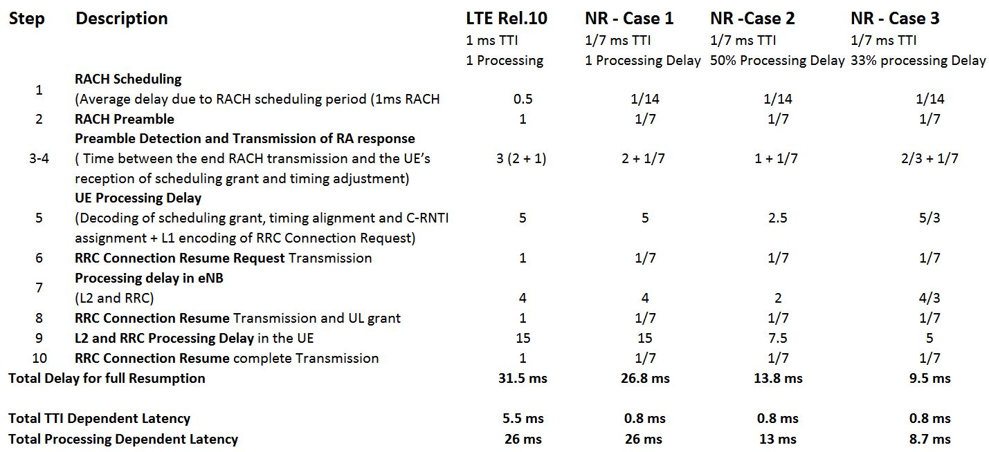
Table below shows the calculated latencies consider all step shown in reference call flow. Here, LTE Release 10 column shows the latency with traditional 1 ms TTI length and UE- eNodeB processing delay as LTE. The analysis for NR can reuse the same approach as LTE but with different system parameters, such as different TTI and different processing delay, due to enhanced hardware capability.
For NR calculation, let us consider a 2-symbol TTI (1/7 ms is the same number of symbols as LTE in a 1 ms sub-frame). For processing delay, lets consider three case including the same processing delay as LTE as case 1, 50% less processing as case 2 and 33% less processing delay as Case 3.

If a 5G gNB is integrated with a LTE eNB, and the control protocol (i.e. RRC) is located in the LTE eNB, the control plane latency will be the same as in the LTE case.
Reference:
- TR 23.799 Study on Architecture for Next Generation System
- TR 38.801 Study on New Radio Access Technology; Radio Access Architecture and Interfaces
- TR 38.804 Study on New Radio Access Technology; Radio Interface Protocol Aspects
- TR 38.913 Study on Scenarios and Requirements for Next Generation Access Technologies
- Samsung White Paper: 4G-5G Interwworking
Related Post
- 5G NR Grant Free Dynamic Scheduling
- 5G NR sounding Reference Signal (SRS)
- 5G NR RACH Preamble Types: Long and Short Preambles
- NR-Logical Channels,Transport Channels and Physical Channels Mapping
- NR Radio Network Temporary Identifier (RNTI)