5G mmWave 28 GHz Band Link Budget – n257
The combination of 5G NR technology and millimeter wave bands pioneer a new level of mobile performance with ultra-high speeds and low latencies. Momentum behind 28 GHz is growing, with the availability of commercial services, devices and large bandwidth up to 850 MHz. The use of antenna arrays and beamforming enables the use of 28GHz band mmWave frequencies for wireless communication.
28 GHz Detailed Specification
- 3GPP Band Naming: n257
- Frequency Rang: 26.50 GHz– 29.50 GHz
- Available BW: 850 MHz
- Channel BW: 50 MHz, 100 MHz, 200 MHz, 400 MHz
- Band Name: LMDS

Link Budget Analysis
From an operator’s point of view, the viability of any new technology depends on fulfilling the business case given by the business model. The business case is governed by two main factors: the required capital expenditure (CAPEX), followed by the cost to operate and maintain the network (OPEX).
CAPEX is driven by following
- No. of cell sites deployed
- Cell edge performance (i.e., the required data rate at the cell edge) and
- Achievable Coverage
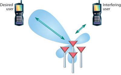
mmWave allows beamforming that helps overcome the higher path loss, but coverage is still limited while compared to frequencies below 6 GHz, the primary spectrum being utilized by service operators. To ensure adequate coverage, a link budget analysis is essential.
Considering the 28 GHz band with 100 MHz carrier bandwidth, first the receiver sensitivity limits needs to be calculated. Lets consider following assumptions
- BW= 100 MHz,
- Required SINR to decode successful 16 QAM,1/2 FEC = 8dB,
- Antenna Array Gain = 17dB
- UE Noise Figure = 10dB
- Estimated Path Loss for a distance 1000 m ISD (500 m cell radius)
- Line of Sight Condition path loss = 133 dB
- Non-Line of sight connections path loss = 156 dB
Step 1: Determinse the Receiver Sensitivity Limits
-
-
- Rx Sensitivity = -174 + 10*log (BW) + Noise Figure
-
- =-174 + 10*log(100*10^6) + 10
- = -174 + 80 +10
- = -84 dBm
-
- Rx Sensitivity = -174 + 10*log (BW) + Noise Figure
-
Step 2: Determines the expected Path loss
-
-
- Line-of-sight connection under ideal conditions : 133 dB
- Non-LOS connections for Fixed Wireless Access (FWA) : 156dB
-
Step 3: Determines the Required Effective Isotropic Radiated Power
-
-
- EIRP = Receiver Sensitivity + SNR – Rx Antenna Gain + Path Loss
- LOS Case
- EIRP = -84 +8 -16 +133 =41dBm
- Non-LOS Case
- EIRP = -84 +8 -16 +156 = 64 dBm
- LOS Case
- EIRP = Receiver Sensitivity + SNR – Rx Antenna Gain + Path Loss
-
Step 4: Decide on the required cell edge performance, i.e., the required data rate
- The data rate per carrier depends on the modulation, MIMO scheme and achievable SNR. A typical requirement is, for example, to achieve a spectral efficiency of 2 bps/Hz, i.e., 200 Mbps for a 100 MHz wide channel. To achieve this, an SNR of around 8 dB is required, which increases the receiver sensitivity limit further.
- However, as the receiver is using an antenna array, beamforming gain is available, determined by the gain of a single antenna element and the total number of elements. A good approximation in this early stage of 5G development is 17 dBi for the total receive beamforming gain.
- Based on the estimated path loss, the required total equivalent isotropic radiated power (EIRP) and the required conducted transmit power can be determined. Given the above calculations, the required total EIRP for the transmit side is between 41 and 64 dBm (see step 2). It is a fair assumption that using a larger antenna array at the 5G remote radio head results in larger beamforming gain.
For mmWave components, these are high output powers, and it is a challenge to the RF hardware designer to design
such power amplifiers and the required circuitry to drive the RF front-end and antenna arrays. As not all substrates
can provide such a high output power, the industry faces a philosophy battle among companies designing these RF components. One of the challenges is to provide components with an acceptable power-added efficiency to handle the heat dissipation.
Based on this analysis, establishing a viable communication link in the downlink direction with an ISD of 1000 m is possible. However, previous generations of wireless technologies were uplink power limited, and 5G is no exception. Below shows the uplink link budget assuming a maximum device power of +23 dBm and the form factor of a customer premise equipment (CPE) router with a 16-element antenna array.
Uplink Link Budget
- Total Tx EIRP: 41 dBm
- Path Loss: 133 to 156 dB
- Bandwidth: 100 MHz
- Thermal Noise: -174 + 10*log(100*10^6) =−94 dBm
- gNB Rx Noise Figure: 6 dB
- Minimum Detectable Signal: −88 dBm
- Required SNR with QPSK and ½ FEC: 5 dB
- Total Rx Beamforming Gain: 24 dBi
- 100 MHz Rx Signal Bandwidth: −107 dBm
- Link Margin = Total Tx EIRP – Path Loss – Rx Signal
- Link Margin* −9 to +14 dB
Depending on the path loss and the assumed channel model, a link margin can be calculated that spans quite a range (i.e., ‐9 to +14 dB). Everything below zero indicates, of course, that the link cannot be matched.
Based on these rather ideal calculations, it can be concluded that an uplink at mmWave frequencies with an ISD of 1000 m is problematic. For that reason, 3GPP defines a 5G NR user equipment (UE) power class that allows a total EIRP of up to +55 dBm.
Current regulations in the U.S. allow a device with such a high EIRP but not in a mobile phone form factor. However, achieving this EIRP is a technical challenge by itself and may come to the market at a much later stage. From that perspective, a service provider should consider a shorter ISD in its business case. Current literature and presentations at various conferences indicate that cell sizes of 250 m or less are being planned for the early stage of radio equipment. Now it needs to be determined if a shorter ISD, such as 250 m, fulfills the business case for 5G mmWave FWA.
Related Posts:
- 5G Network RF Planning – Link Budget Basics
- 5G mm Wave 28GHz Band Link Budget-n257
- 5G NR Physical Cell ID (PCI) Planning
- 5G NR Network Relationship – Neighbor Planning