What is directivity in a coupler ?
Directional couplers are four-port circuits where a defined amount of the electromagnetic power fed at the input port in a transmission line is coupled to a port (known as coupled port) and one port is isolated from the input port.
One key feature of directional couplers is that they only couple power flowing in one direction. In this way, power entering the output port is coupled to the isolated port but not to the coupled port.
Below is the example for a 6dB coupler:

Directivity is a measure of how well the coupler isolates two opposite-traveling (forward and reverse) signals at the coupled port.
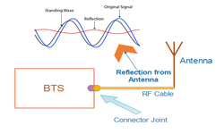
The importance of directivity is illustrated in the following example. Suppose we want to measure the power traveling down a transmission line terminated by unknown impedance. Using a coupler, we can couple off some fraction of power (e.g. 1%) and measure it with a detector. If the DUT impedance is perfectly matched to the transmission line, then no reflection will be generated (therefore regardless of whether the coupler has directivity or not, we will measure the correct power).

Now suppose the DUT is non-ideal and generates a reflection. Some of the reflected wave will ‘leak’ into the coupled port due to non-ideal directivity. This ‘leakage’ will interfere with the desired forward coupled signal and cause error in the forward power measurement as shown below:

So, here directivity comes into picture. Directivity is the ratio of coupled power to the isolated power as describes by the formula as below:

Where D is the directivity, S31 is the coupling ratio, and S32 is the isolation
It means that better the directivity of a coupler, there will be less leakage from the reflected power to the coupled port and hence the forward power measurement will be more accurate.


