Signal to Interference and Noise Ratio (SINR)
SNIR is a measure of Signal Quantity and Interference and Noise Quantity and it is very important measurement in terms of RF and sometime it is also called as SNR in absence of interference. It indicate how much desired signal is stronger compare to Noise and interference. Its unit is dB.Mathematical it can be express as
 To understand it better lets take an example. Let’s one say SNR of 30 dB, it means the desired signal power is 30 dB better than noise power. If we convert 30dB in to linear scale it means the desired signal power is 1000 time better than the noise power.
In LTE , we can find many SNR like Reference Signal SNR (RS SNR), PDSCH SNR , PUSCH SNR and PUCCH SNR and each have its own significance.
RS SNR is useful for channel detection and PDSCH SNR of Data decoding,PUSCH SNR and PUCCH SNR is applicable for Uplink data and Control channel detection. Each channel have its minimum level SNR requirements for detection. This SNR requirement depend on the modulation means to decode 64 QAM the SNR should be high close to 25 dB or more and likewise to decode an QPSK it is low may be about 2dB or less. Each channel in LTE uses particular modulation so SNR requirement is also accordingly.
SNR and RSRP Relation
RSRP is measured on a LTE single sub-carrier i.e. 15KHz and similary SNR can also be measured per sub-carrier (Narrow Band SNR) or over a certain number of sub-carriers (Wide band SNR).
So to find SNR we first need to calculate noise Power. As per physics we know each Hz bandwidth has a noise power of -174dBm/Hz, so we can calculate it for 15KHz using following formula
Noise Power (dBm)= -174 +10*log(Bandwidth in Hz)
= -174 + 10*log(15*1000) =-132.23 dBm
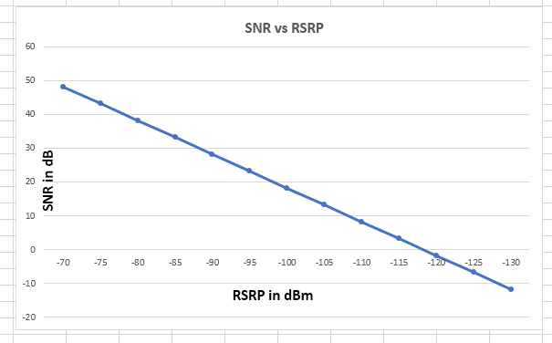
UE normally has a noise figure of 7 dB then then Rx sensitivity for one sub-carrier will be -125.23 dBm (-132.23 +7). It means if UE is experience SNR of 0 dB then it should be able to decode a 15Khz signal when the received power is equal to or better than -125.23 dBm, so we can assume RSRP -125dBm is equal to 0dB SNR consider single antenna case, while with 2 antenna case the SNR will be double means 3dB. To make it clear this relation is valid only with one signal source and no interference. so using this assumption we can get a plot as shown in figure.
| RSRSP in dB | SNR in dB 1 Antenna | SNR in dB 2 Antenna |
|---|---|---|
| – 70 dBm | 48.2 dB | 51.2 dB |
| – 75 dBm | 43.2 dB | 48.2 dB |
| – 80 dBm | 38.2 dB | 43.2 dB |
| – 85 dBm | 33.2 dB | 38.2 dB |
| – 90dBm | 28.2 dB | 33.2 dB |
| – 95 dBm | 23.2 dB | 28.2 dB |
| – 100 dBm | 18.2 dB | 23.2 dB |
| – 105 dBm | 13.2 dB | 18.2 dB |
| – 110 dBm | 8.2 dB | 13.2 dB |
| – 115 dBm | 3.2 dB | 8.2 dB |
| – 120dBm | – 1.8 dB | 3.2 dB |
| – 125 dBm | – 6.8 dB | -1.8 dB |
| – 130 dBm | -11.8 dB | -6.8 dB |
Related Posts:
- RSRP (Received Signal Received Power)
- RSSI (Received Signal Strength Indicator)
- RSRQ (Received Signal Received Quality)
- Signal to Noise Ratio
- LTE FDD System Capacity and Throughput Calculations
- LTE TDD Special Subframe and Its significance for Cell Size


