MASTER INFORMATION BLOCK (MIB)
MASTER INFORMATION BLOCK (MIB) is the broadcast information transmitted by eNodeB at periodically. After Decoding the PSS and SSS information UE have the information of Physical cell ID and not it can descramble the further information which Master information Block, which will provide the System bandwidth, Antenna configuration , System frame number.
Bits and Bytes of Master information blocks:
- Logical Channel – BCCH (Broadcast common control Channel)
- Transport Channel – BCH (Broadcast Channel)
- Physical Channel – PBCH (Physical Broadcast channel)
- RLC Mode – ™(Transparent Mode)
- Size of Master Information Block – 24 Bits
- Resource Block Requirement – MIB require 6 RBs (72 subcarriers) in Frequency domain
- Location in Resource Grid – 4 symbols of first subframe second slot symbol 0, 1, 2 and 3.
- Channel Coding – tail bit convolutional encoding
- Rate matching – 1/16 Rate coding (repetition coding)
- Modulation – QPSK

Message content of MIB as per 3gpp 36.331
MasterInformationBlock ::= SEQUENCE {
dl-Bandwidth ENUMERATED { n6, n15, n25, n50, n75, n100},
phich-Config PHICH-Config,
systemFrameNumber BIT STRING (SIZE (8)),
spare BIT STRING (SIZE (10))
}
All above content is sent as 24bits binary information and these 21bits can be splitted as below:
3 bits for system bandwidth (000-111 )
3 bits for PHICH information,(1 bit to indicate normal or extended PHICH , 2 bit to indicate the PHICH Ng value)
8 bits for system frame number
10 bits are reserved for future use
Apart from the above information, the MIB CRC also provides the number of transmit antennas used by the eNodeB. The MIB CRC is scrambled with an antenna specific mask.
To get know more about the transmission and Generation of Master Information please read our post on Physical Broadcast channel
Physical Broadcast channel is a physical layer channel and carried the Master Information Block. It is mapped Logical channel as BCCH and Transport channel as BCH. It occupies central 6 RBs (72 Subcarrier) in frequency domain and mapped on 4 symbols of first subframe second slot symbol 0, 1, 2 and 3. PBCH channel uses QPSK modulation.
Below is the
PBCH Transmission :
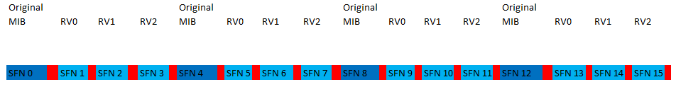
The MIB information is generated at every 40 ms or we can say after every 4 System frame number and sent to physical layer for encoding. Now Physical layer transmits it at every 10 ms or we can say it broadcast it every system frame number. Physical layer transmits new MIB information only at SFN mode 4=0 and at other SFN is only transmits the redundancy version. The below Picture depict the same. All Dark blue are the New MIB which may or may not change every 40ms and light blue are the RV (Redundant Version) of Original MIB
The MIB payload worth 24 bit is received from upper to physical layer and the physical layer do the following process,
CRC Generation – Here a 16 bit CRC is generated by the CRC module and it is scrambled with a antenna specific mask and same mask is used by UE while find out the antenna configuration.
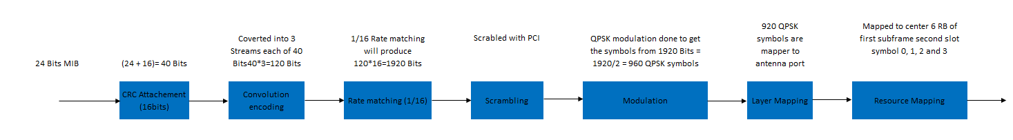
CRC attachment to MIB – The generated CRC is attached to the MIB payload after which the size of the payload will be 40 bits (24 bit of MIB + 16 bit of CRC)
Convolutional encoding – A tail bit convolutional encoding is performed over the 40 bits and the output is 3 streams of 40 bits each
Rate matching – The rate matching here is nothing but a repetition coding, where the 3 streams of size 120 bits (40×3 bits) is just repeated 16 times to get 1920 bits. The repetition rate is very high since the MIB is a very vital information and the UE cannot afford to lose it.
Scrambling – These 1920 bits are scrambled with a scrambling sequence as long as 1920 bits
Modulation (QPSK) – A QPSK modulation is performed over these 1920 bits to obtain 960 complex QPSK symbols (Symbols = Total no of bits/Bits per Symbol)
This is the basic operation for PBCH encoding, but since the PBCH has to be transmitted every 10 milliseconds on subframe 0 of all radio frames, the PBCH modulation buffer is divided into 4 sub-buffers each as long as 240 complex symbols. Each sub-buffer is transmitted over PBCH and by the time the last sub buffer is transmitted on PBCH, a new MIB is arrived from higher layer which is again encoded using the above method and the process continues

As you see from the above diagram, a new MIB is generated by higher layers whenever the System frame number satisfies the condition (System Frame Number Modulo 4 is zero) SFN%4=0. you may know that PBCH output is 960 complex symbols long and that is divided into 4 parts and each parts are transmitted in consecutive System frames, which can also be seen the diagram, where the first 240 bits goes in SFN-0, the next 240 bits in SFN-1 and so on. Just to note, each individual PBCH are independently decodable, what I mean here is, if the UE finds the PBCH in SFN-0 he can still decode the all contents of MIB without waiting for the parts of the PBCH in coming in next System frame.
Related Posts:
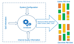
- LTE eNodeB Schedulers and Different Scheduling Types
- LTE EUTRAN Bands
- Feature Group Indicators (FGI bits) in LTE Rel. 8, Rel. 9, Rel. 10
- Dual Connectivity (DC) Definition, Protocol Architecture, DC and CA Comparison
- Multi Carrier Cell Reselection in LTE
- Maximum Coupling Loss (MCL) and Maximum Path Loss (MPL)