5G NR RSRP Measurement Report Mapping
In 5G NR, RSRP measurement is performed and reported at Layer 1 (Physical Layer) and Layer 3 (RRC Layer). For example, 5G capable device can provide SS-RSRP measurements at Layer 1 when sending Channel State Information (CSI) and at Layer 3 when sending an RRC: Measurement Report to gNB.
How Measurement is performed
To generate SS-RSRP measurement results, 5G UE is allowed to measure PBCH-DMRS signal. DMRS and SS signals are transmitted with equal power so results can be averaged.
While performing SS-RSRP measurements for L1, UE can be configured to measure CSI-RS as well. CSI-RS may be transmitted with different transmit power compared to Sync Signals (SS) and PBCH-DMRS. In this case gNB shall provide offset information to UEs so that it can be taken into account during the measurement.
Measurement Characteristics
- Layer 3 (L3) Measurement:
-
- L3 measurements are useful for radio resource management decisions which require a long term view of channel conditions, e.g. handover procedures should be triggered after Layer 3 filtering to reduce the risk of ping-pong between serving cells
- Measurements are filtered at Layer 3 to remove the impact of fast fading and to help reduce short term variations in results
- L3 measurements can be either ‘beam level’ or ‘cell level’ which can be reported within an RRC message: Measurement Report (MR)
- Beam level measurements are generated directly from the L1 measurements by applying L3 filtering
- Cell level measurements are derived from the L1 measurements using the certain rules
- L3 SS-RSRP reporting range is defined from -156 dBm to -31 dBm with 1 dB resolution
- L3 report requires 7 bits payload to represent 128 value mapped to RSRP in dB
-
- Layer 1 (L1) Measurement:
-
- L1 measurements are useful for procedures which must react with minimal delay, e.g. beam management procedures which require the UE to rapidly switch between beams
- Measurements are filtered at Layer 1 to help remove the impact of noise and to improve measurement accuracy
- L1 measurements are ‘beam level’
- L1 SS-RSRP and CSI-RSRP reporting range is defined from -140 to -40dBm with 1dB resolution
- L1 measurement requires 7 bits payload to represent 128 value mapped to RSRP in dB
-
RSRP Measurement Report Mapping
Below table depicts the measurement report mapping for L3 SS-RSRP, L1 SS-RSRP and L1 CSI-RSRP. We have two table available from 3GPP specification 38.133 Table (A) for single value reporting and Table (B) for differential SS-RSRP and CSI-RSRP.
- L3 measurement for SS-RSRP reporting range is defined from -156 dBm to -31 dBm with 1 dB resolution
-
- Reported value of 0 means SS-RSRP is greater or equal to -156dB
- Reported value of 126 means SS-RSRP is less than or equal -31 dBm
- RSRP value rough estimation can be done with following thumb rule formula
- RSRP value = Reported Value – 156
- RSRP in dBm = 111 – 156 = -45 dBm
-
- L1 measurement for SS-RSRP and CSI-RSRP reporting range is defined from -140 dBm to -40 dBm with 1dB resolution
-
- Reporting range value of 0 to 16 and 113 to 127 is not valid for L1 measurement
- Reported value of 17 means SS-RSRP is greater or equal to -156dB
- Reported value of 112 means SS-RSRP is less than or equal -45 dBm
- RSRP value rough estimation can be done with following thumb rule formula
- RSRP value = Reported Value – 156
- RSRP in dBm = 18 – 156= -138 dBm
-
- The reporting range of differential SS-RSRP and CSI-RSRP for L1 reporting is defined from 0 dBm to -30 dB with 2 dB resolution
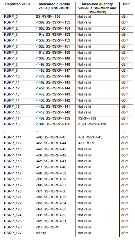 Table (A)
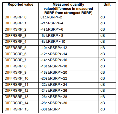 Table (B)
Reference:
Related Post: