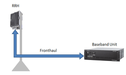
O-RAN Fronthaul Transport Synchronization Configurations
O-RAN maintains network timing distribution as the preferred approach within the fronthaul network. Time and frequency synchronization needs to be distributed to O-DU and O-RU for the effective O-RAN network operation. The loose sync can cause serious negative impact on network KPIs e.g. low throughput, poor attach success rate and poor handover success rate.
O-RAN fronthaul can have following synchronization options over an Ethernet network:
- Frequency Sync where clocks are aligned in frequency
- Phase Sync where clocks are aligned in phase
- Time Sync where clocks are aligned to a common base time
The accuracy of sync is mostly depend on implementation (e.g., timestamping near the interfaces, number of hops). Open fronthaul networks can be synchronized in several modes and O-RAN CUS Specification WG4 has defined following four configurations.
- Configuration LLS-C1 (LLS-C1)
- Configuration LLS-C2 (LLS-C2)
- Configuration LLS-C3 (LLS-C3)
- Configuration LLS-C4: (LLS-C4)
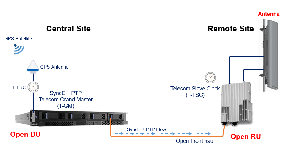
Configuration LLS-C1 is based on point-to-point connection between O-DU and O-RU using network timing option. It is basically the simplest topology for network timing option, where O-DU directly synchronizes O-RU.
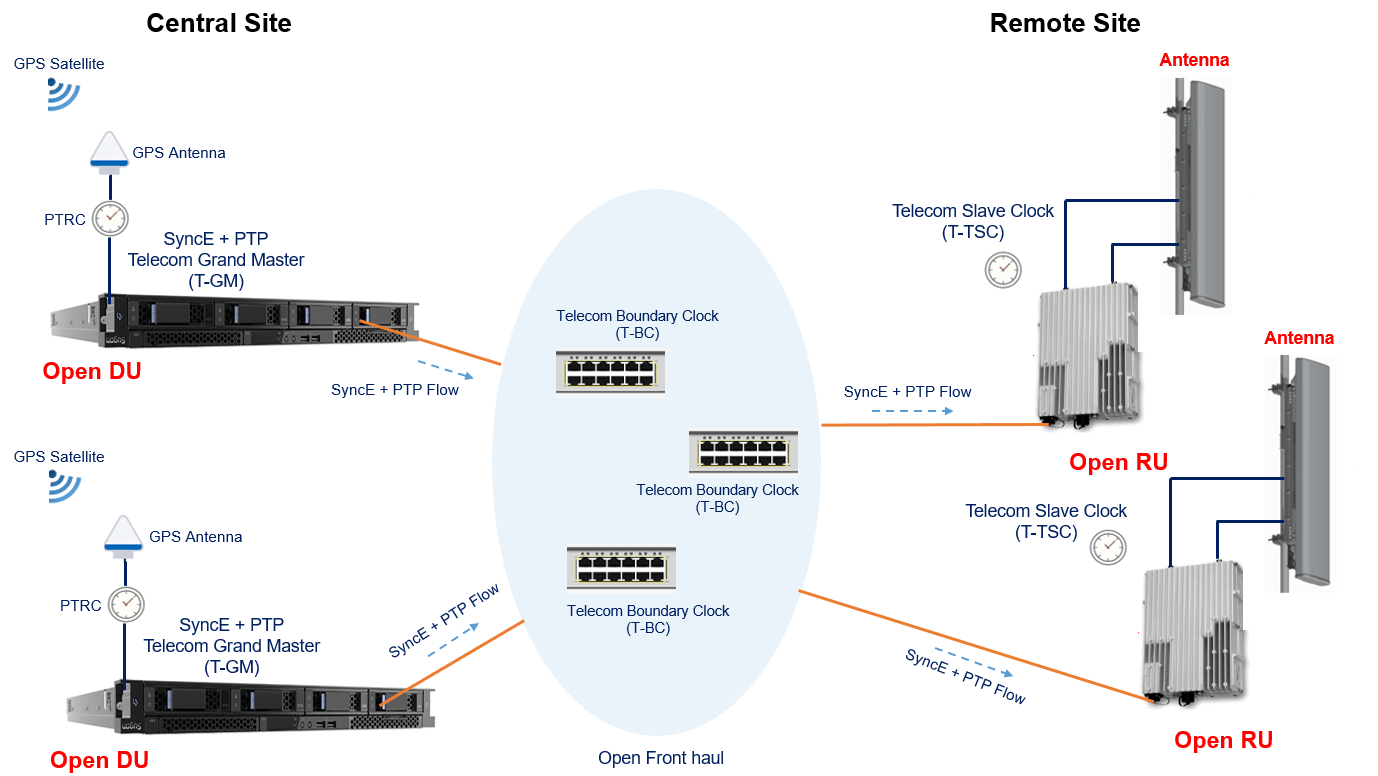
Configuration LLS-C2 is somewhat similar to LLS-C1 where O-DU acting as PTP and SyncE master to distribute network timing toward O-RU. The synchronization SYNCE+PTP master is located at the O-DU. Further, all Ethernet switches in the fronthaul function as Telecom Boundary Clocks (T-BC). One or more Ethernet switches are allowed between the O-DUs at central site and the O-RUs at remote site. The allowed no. of switches in the PTP and SyncE path is limited by frequency and time error contributions by all clocks in the chain. Interconnection among switches and fabric topology (e.g. mesh, ring, tree, spur etc.) can be done based on deployment scenario. Frequency and Timing budgets and network configuration to ensure 4G and NR Timing Alignment Error requirements and frequency accuracy requirements should be met.
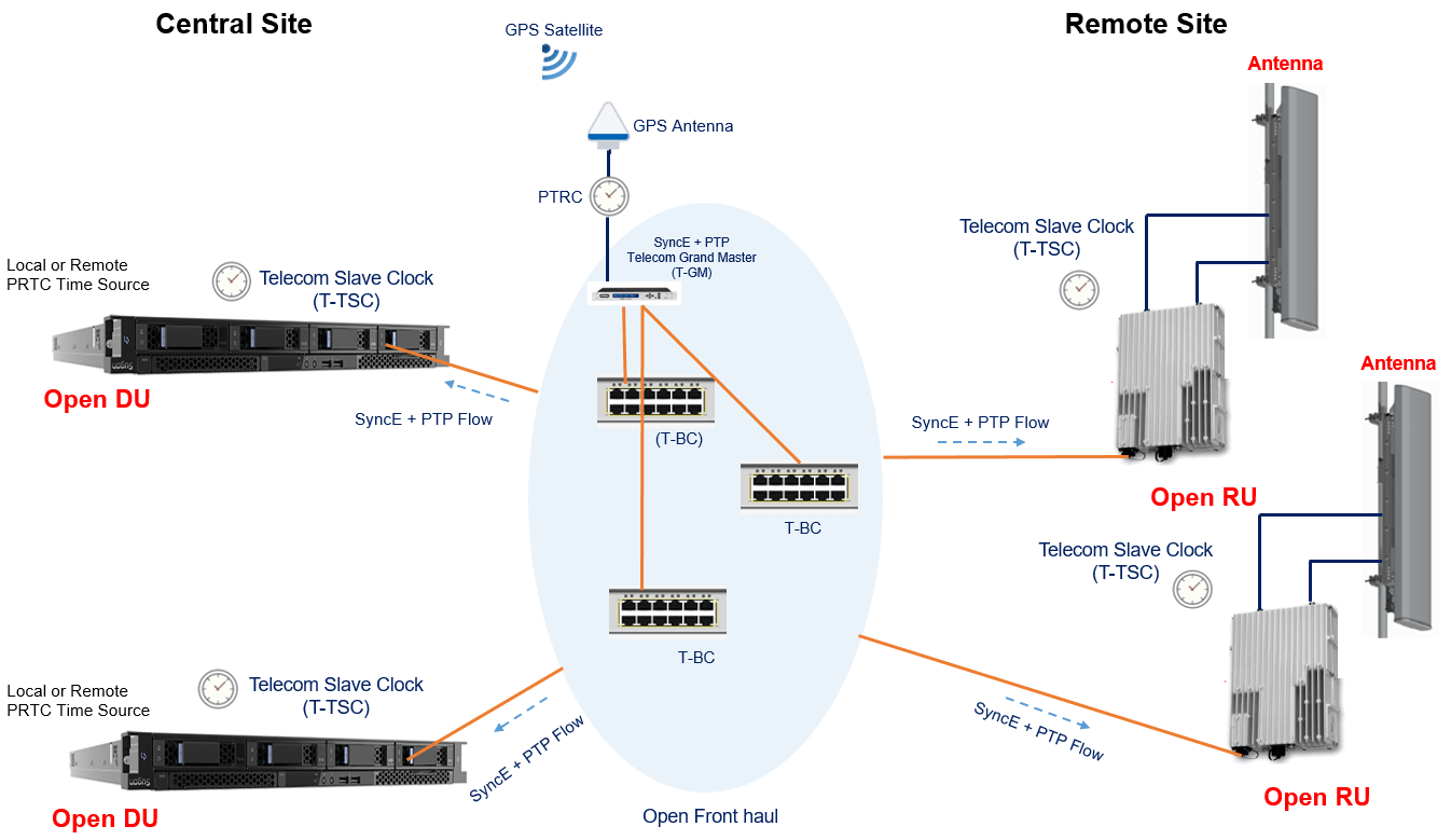
Configuration LLS-C3 support network timing distribution from PRTC/T-GM to O-RU between central sites and remote sites. It means that one or more PRTC/T-GM (acting as SYNCE+PTP master) can be implemented in the fronthaul network to distribute network timing toward O-DU and O-RU as shown in following figure.
- A network topology of Ethernet switches can be used in the fronthaul transport network.
- Interconnection among switches and fabric topology (for example mesh, ring, tree, spur etc.) are deployment decisions.
- O-DU does not act as SYNCE and PTP Master towards the fronthaul interface. It can select its own synchronization from local or remote PRTC like in LLS-C1/LLS-C2, but can also select the same SYNCE and PTP distribution from the fronthaul as the O-RU
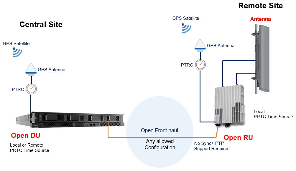
Configuration LLS-C4 use a local PRTC (typically a GNSS receiver) providing the timing to O-RU and does not depend on fronthaul for timing and sync. Such configuration timing support at O-RU requires extra timing interface or embedded circuit within O-RU which may increase cost.
Reference:
Related Post:
- O-RAN Fronthaul C/U, Synchronization and Management Planes
- O-RAN Fronthaul Protocols Stack
- O-RAN Fronthaul Delay Management
- O-RAN RU Reference Architecture