5G NR Dual Active Protocol Stack (DAPS) Handover – 3GPP Release 16
3GPP Definition: As per 3GPP TS 38.300 DAPS Handover can be defined as a handover procedure that maintains the source gNB connection after reception of RRC message (HO Command) for handover and until releasing the source cell after successful random access to the target gNB.
DAPS Handover Characteristics:
- UE continue Tx/Rx at the source cell after receiving the HO request
- UE performs simultaneous reception of user data from source and target cell
- UE switch uplink transmission of user data to target cell after completion of RACH procedure
- DAPS reduces interruption during handover close to 0 ms, by maintaining the source cell radio link (including data flow) while establishing the target cell radio link
- DAPS handover is possible over both interface Xn and N2
- A DAPS Handover can be used for an RLC-AM or RLC-UM bearer
Why DAPS Handover Required?
In Legacy 4G LTE networks and 5G NR till release 15, the UE typically releases the connection from the source cell before the connection is established with the target cell (Hard Handover). Due to this, UL and DL transmission is finalized at source cell before the UE starts to communicate with the target cell results an interruption of a few tens of milliseconds in the communication between the UE and the base station. This interruption is very critical for URLCC use case /application with in 5G.
So 3GPP has proposed a solution to overcome this problem as part of Release 16 named as Dual Active Protocol Stack (DAPS) where UE connection with source cell to remain active for Rx and Tx of user data, until it is able to send and receive user data in the target cell. This put a new requirement at UE side to simultaneously receive and transmit data at both source cell and target cell for a short time period during the handover procedure. In my view, this is similar to soft handover procedure.
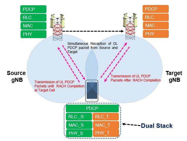
As shown in above picture, to support DAHO, UE has to keep Dual Stack in Active state. One user plane protocol stack for the target cell, containing PHY (Physical), MAC (Medium Access Control) and RLC (Radio Link Control) layers, while keeping the second user plane protocol stack active for transmission and reception of user data in the source cell.
UE receives user data simultaneously from both the source and target cell, the PDCP (Packet Data Convergence Protocol) layer is reconfigured to a common PDCP entity for the source and target user plane protocol stacks. To secure in-sequence delivery of user data, PDCP Sequence Number (SN) continuation is maintained throughout the handover procedure. For that reason, a common (for source and target) re-ordering and duplication function is provided in the single PDCP entity. Ciphering/deciphering and header compression/decompression need to be handled separately in the common PDCP entity, depending on the origin/destination of the downlink/uplink data packet.
DAPS Handover Call Flow:
DAPS handover call flow is shown in following figure. DAPS handover is possible over both interface Xn and N2 interface. Here we have consider HO based on Xn interface.
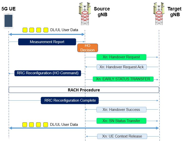
- The source gNB configures the UE measurement procedures and the UE reports Measurement Report according to the Meas Config . The source gNB decides to handover the UE, based on Measurement Report and RRM information
- The source gNB issues a Handover Request message to the target gNB passing a transparent RRC container with necessary information to prepare the handover at the target side.
- The target gNB prepares the handover and sends the HANDOVER REQUEST ACKNOWLEDGE to the source gNB, which includes a transparent container to be sent to the UE as an RRC message to perform the handover. The target gNB also indicates if a DAPS Handover is accepted
- The source gNB triggers the Uu handover by sending an RRC Reconfiguration message to the UE
- For DRBs configured with DAPS, the source gNB sends the EARLY STATUS TRANSFER
- The UE synchronizes to the target cell and completes the RRC handover procedure by sending RRC Reconfiguration Complete message to target gNB
- Target gNB sends the HANDOVER SUCCESS message to the source gNB to inform that the UE has successfully accessed the target cell
- Source gNB sends the SN STATUS TRANSFER message for DRBs configured with DAPS as per EARLY STATUS TRANSFER
Bearer Handling with DAPS handover
A DAPS Handover can be used for an RLC-AM or RLC-UM bearer. For a DRB configured with DAPS, the following principles are additionally applied.
- Downlink:
- During HO preparation, a forwarding tunnel is always established.
- The source gNB is responsible for allocating downlink PDCP SNs until the SN assignment is handed over to the target gNB and data forwarding. That is, the source gNB does not stop assigning PDCP SNs to downlink packets until it receives the HANDOVER SUCCESS message and sends the SN STATUS TRANSFER message to the target gNB
- Upon allocation of downlink PDCP SNs by the source gNB, it starts scheduling downlink data on the source radio link and also starts forwarding downlink PDCP SDUs along with assigned PDCP SNs to the target gNB
- For security synchronisation, HFN is maintained for the forwarded downlink SDUs with PDCP SNs assigned by the source gNB. The source gNB sends the EARLY STATUS TRANSFER message to convey the DL COUNT value, indicating PDCP SN and HFN of the first PDCP SDU that the source gNB forwards to the target gNB
- HFN and also PDCP SN are maintained after the SN assignment is handed over to the target gNB. The SN STATUS TRANSFER message indicates the next DL PDCP SN to allocate to a packet which does not have a PDCP sequence number yet, even for RLC-UM
- During handover execution period, the source and target gNBs separately perform ROHC header compression, ciphering, and adding PDCP header
- During handover execution period, the UE continues to receive downlink data from both source and target gNBs until the source gNB connection is released by an explicit release command from the target gNB
- During handover execution period, the UE DAPS PDCP maintains separate security and ROHC header decompression associated with each gNB, while maintaining common reordering function, duplicate detection, discard function, and PDCP SDUs in-sequence delivery to upper layers. PDCP SN continuity is supported for both RLC AM and UM DRBs configured with DAPS.
- Uplink:
- The UE transmits UL data to the source gNB until the random access procedure toward the target gNB has been successfully completed. Afterwards the UE switches its UL data transmission to the target gNB.
- Even after switching its UL data transmissions, the UE continues to send UL L1 CSI feedback, HARQ feedback, L2 RLC feedback, ROHC feedback, HARQ data re-transmissions, and RLC data re-transmission to the source gNB.
- During handover execution period, the UE maintains separate security context and ROHC header compressor context for uplink transmissions towards the source and target gNBs. The UE maintains common UL PDCP SN allocation. PDCP SN continuity is supported for both RLC AM and UM DRBs configured with DAPS.
- During handover execution period, the source and target gNBs maintain their own security and ROHC header decompressor contexts to process UL data received from the UE.
- The establishment of a forwarding tunnel is optional.
- HFN and PDCP SN are maintained in the target gNB. The SN STATUS TRANSFER message indicates the first missing UL COUNT that the target should start delivering to the 5GC, even for RLC-UM.
Upon receiving DAPS handover command message, the UE suspends source cell SRBs, stops sending and receiving any RRC control plane signalling toward the source cell, and establishes SRBs for the target cell. The UE releases the source cell SRBs configuration upon receiving source cell release indication from the target cell after successful DAPS handover execution. When DAPS handover to the target cell fails and if the source cell link is available, then the UE reverts back to the source cell configuration and activate source cell SRBs for control plane signalling.
References
- 3GPP TS 38.300 5G NR and NG-RAN Overall description; Stage-2 ( version 16.2.0)
- Reducing mobility interruption time in 5G networks
Related Post
- 5G NR RRM Measurement Requirements
- 5G NR Measurement – Serving Cell and Neighbor Cell
- 5G NR Measurement Events
- 5G NR Measurement Configuration: Meas Object, Report Config, Meas ID
- 5G NR Measurement Gap Configuration