LTE Control Plane and User Plane Latency Calculation (FDD)
LTE- is designed to support peak data rates of 300 Mbps in the downlink and 75 Mbps in the uplink with 4×4 MIMO support along with C-Plane latency less than 100ms and U-Plane latency less than 10ms.
Latency is defined as the average time between the transmission of packet and the reception of an acknowledgment. Low latency is a key performance index for better user experience. There are several applications that do not require very high data rate, but they do require low latency. Voice, real time gaming and interactive applications are some examples.
Control Plane Latency Defination
Control plane deals with signaling and control functions, while user plane deals with actual user data transmission. C-Plane latency is measured as the time required for the UE (User Equipment) to transit from idle state to active state. In idle state, the UE does not have an RRC connection. Once the RRC is setup, the UE transitions to connected state and then to the active state when it enters the dedicated mode.
Control Plane Latency Calculation:
In idle state the UE doesn’t have an RRC connection. UE monitors the paging channel to detect the incoming calls and acquire system information. Once the UE moves to connected state, it establishes an RRC connection and a radio bearer. Figure below shows the message flow and steps involved in idle to connected transition.
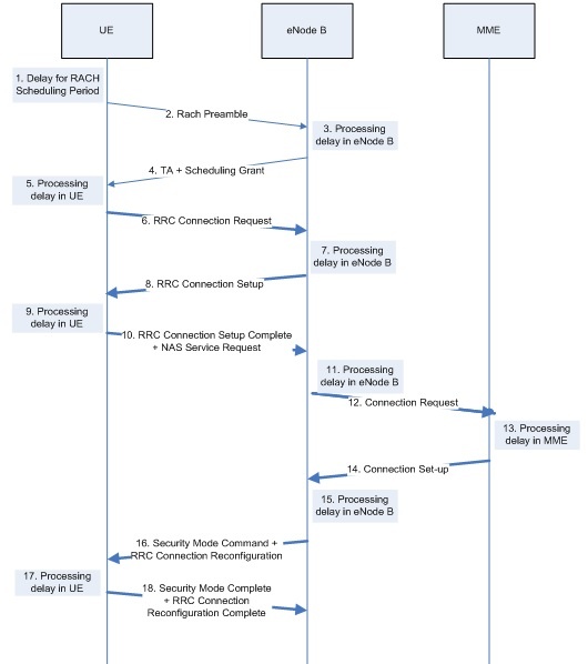
- UE waiting for RACH scheduling
- RACH preamble to eNB
- Preamble detection at eNB
- Transmission of RA response (Time between the end RACH transmission and UEs reception of scheduling grant and timing adjustment)
- Decoding of scheduling grant, timing alignment and CRNTI assignment at UE
- Transmission of RRC connection request to eNB
- L2 and RRC processing delay at eNB
- Transmission of RRC Connection Setup to UE (Simultaneously NAS service is requested and processed) 9. L2 and RRC processing delay at UE
- Transmission of RRC Connection Setup Complete to eNB.
- Transmission of RRC Connection Set-up complete (including NAS Service Request)
- Processing at eNB (Uu–S1-C)
- NAS connection request, S1-C transfer delay
- MME processing
- NAS connection setup, S1-C transfer delay
- Processing at eNB
- Transmission of RRC Security Mode Command and Connection Reconfiguration (+TTI alignment) to UE
- L2 and RRC processing at UE
- Transmission of setup complete to eNB
Table below provides a timing analysis, assuming FDD frame structure, of the flow depicted in Figure above. The analysis illustrates that the state transition from IDLE to CONNECTED can be achieved within a minimum of 76ms, with 3ms msg2 window and 1ms PRACH cycle. Considering more reasonable values (5ms msg2 window and 5ms PRACH cycle), a 80ms transition time is achieved.
| Component | Description | Minimum
[ms] |
Average
[ms] |
| 1 | Average delay due to RACH scheduling period | 0.5 | 2.5 |
| 2 | RACH Preamble | 1 | 1 |
| 3-4 | Preamble detection and transmission of RA response (Time between the end RACH transmission and UE’s reception of scheduling grant and timing adjustment) | 3 | 5 |
| 5 | UE Processing Delay (decoding of scheduling grant, timing alignment and C-RNTI assignment + L1 encoding of RRC Connection Request) | 5 | 5 |
| 6 | Transmission of RRC Connection Request | 1 | 1 |
| 7 | Processing delay in eNB (L2 and RRC) | 4 | 4 |
| 8 | Transmission of RRC Connection Set-up (and UL grant) | 1 | 1 |
| 9 | Processing delay in the UE (L2 and RRC) | 15 | 15 |
| 10 | Transmission of RRC Connection Set-up complete (including NAS Service Request) | 1 | 1 |
| 11 | Processing delay in eNB (Uu –> S1-C) | 4 | 4 |
| 12 | S1-C Transfer delay | T_S1 | T_S1 |
| 13 | MME Processing Delay (including UE context retrieval of 10ms) | 15 | 15 |
| 14 | S1-C Transfer delay | T_S1 | T_S1 |
| 15 | Processing delay in eNB (S1-C –> Uu) | 4 | 4 |
| 16 | Transmission of RRC Security Mode Command and Connection Reconfiguration (+TTI alignment) | 1.5 | 1.5 |
| 17 | Processing delay in UE (L2 and RRC) | 20 | 20 |
| Total delay [ms] | 76 | 80 |
In latency calculation figures Step 12 and 14 are not included because these are core network latency and depends on many factors like transport network, routing delay, network congestion etc.
User Plane Latency
U-Plane latency is defined as one-way transmit time between a packet being available at the IP layer in the UE/E-UTRAN edge node and the availability of this packet at the IP layer in the E-UTRAN/UE node. U-Plane latency is relevant for the performance of many applications. This tutorial presents in detail the delay budgets of C-Plane and U-Plane procedures that add to overall latency in state transition and packet transmission.
User Plane Latency Calculation
The LTE U-plane one way latency for a scheduled UE (RRC connected) consists of the fixed node processing delays (which includes radio frame alignment) and 1ms TTI duration for FDD as shown in Figure below:
Considering that the number of HARQ processes is fixed to 8 for FDD, the one-way latency can calculated as:
- DUP [ms] = 1.5 + 1 + 1.5+ n*8 = 4 + n*8,
where n is the number of HARQ retransmissions. Considering a typical case where there would be 0 or 1 retransmission, the approximate average U-plane latency is given by:
- DUP,typical [ms] = 4 + p*8,
where p is the error probability of the first HARQ re-transmission. The minimum latency is achieved for a 0% BLER, but a more reasonable setting is 10% HARQ BLER.
- DUP,0%HARQ_BLER [ms] = 4 (0% HARQ BLER)
- DUP,10%HARQ_BLER [ms] = 4.8 (10% HARQ BLER)
Reference:
3GPP TR 36.912 V14.0.0 (2017-03): Annex B: Latency performance of Rel-8
Related Posts:
- RSRP (Received Signal Received Power)
- RSSI (Received Signal Strength Indicator)
- RSRQ (Received Signal Received Quality)
- Signal to Noise Ratio
- LTE FDD System Capacity and Throughput Calculations