How to get better ACLR in TX chain ?
If you are trying to debug the bad ACLR in TX Chain or you are designing a TX for your system, then you must take care following points with regards to better ACLR.
PA Linearity
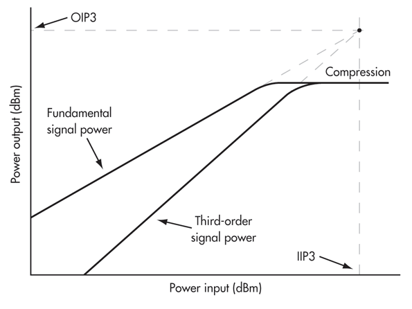
In terms of PA, if the output power of the PA is too high, near to compression point, then IIP3 and IIP5 products produced in the adjacent channel will also be too high in power. And these high power IMD products falls under adjacent channel causes high ACLR. It is the reason that poor ACLR occurs at maximum power.

To improve ACLR in this case is to either reduce the input power of the PA or choose a high linear PA.
Losses from PA output to Antenna Port
As we seen in the first case, ACLR gets poor at maximum powers. One way to reduce PA output high power is to reduce the losses from PA output to antenna connector. Suppose, one need +23dBm power at the antenna port, and if there is 4dB loss between the PA output and Antenna, then we need to get +27dBm power out from PA. And if suppose, loss between the PA output and antenna is +2dB, then we need to get +25dBm power out from PA. So, less is the post PA loss, less output power from PA is required, and so IMD products would be less and so ACLR would be better.
One can reduce post PA losses by considering low loss components and improving transmission line losses on the PCB.
Clean Input to PA
If suppose, there are multiple amplifiers in the TX chain, then the final stage PA input should be clean. Means if the ACLR of driver amplifier (feeding to final stage PA) itself is too bad, then ACLR of final stage amplifier will also be bad. One way is to use band pass filter at the input of final stage amplifier which will reduces the harmonics and improve the ACLR at the input of final stage power amplifier, so the overall ACLR of TX chain will improve.
PA Drain Voltage
If suppose PA datasheet recommends +5V for VCC voltage and you supply the same +5V in your circuit. And it may happen that due to IR losses in the VCC supply lines due to high resistance of inductor or ferrite bead used the supply voltage, the actual voltage reaching to PA drain is +4.8V, then due to less VCC voltage, ACLR will get poor. Higher and better is the VCC, more linear is the PA.
PA Output matching
You can simulate or ask PA vendor to provide PA output matching points for best ACLR. Then you can match the PA output at given impedance points for better ACLR.
Envelop Tracking (ET) calibration
Envelop tracking is one way to improve the ACLR or linearity of the TX chain. It has two types, one is Analog Envelop tracking and the other is Digital Envelop tracking. If Envelop tracking is being used in your system, then proper calibration is required. If it is not properly calibrated then there would be misalignment between VCC supply and envelop of RF signal at the PA input which would cause the bad ACLR.
NOTE: Generally speaking, one can improve the TX chain ACLR, but it comes at the cost of efficiency. Better is the PA linearity, efficiency will be poor, means PA current consumption will be more. There is always a trade-off between these two terms and system designer has to compromise at some stage.
Related Post