How Conventional AGC (Automatic Gain Control) works in receiver chain and its important parameters.
In wireless communication systems such as LTE, the received signal has an unpredictable signal power and varies over a wide dynamic range caused by multi-path fading channel and unwanted signals such as strong interferer signal. Therefore, an AGC is necessary for reducing unwanted signals and dynamically adjusting the AGC gain of the incoming signal to prevent the quantization error or saturation at the ADC (Analog-to-Digital Converter). If large signal levels are detected at the ADC converter, the receiver gain may have to be re-distributed by reducing the pre-conversion analog gain and increasing the digital gain to maintain the desired signal output level.
Purpose of using AGC
Automatic Gain Control Algorithm continuously monitor received power and/or received I and Q baseband signals and decide how much gain to be changed in LNA and VGA modules.
The purpose of the automatic gain control (AGC) algorithm is to regulate the received signal strength at the input of the ADCs such that the required signal SNR for proper decoding is met. For example, if the received signal strength is weak at the antenna, the AGC algorithm boosts the receiver gain stages in order to minimize the noise and bring the signal level to an acceptable SNR. Likewise, if the received signal strength is strong, the AGC algorithm attenuates the receiver gain stages in order to avoid signal clipping and nonlinear degradation’s that would otherwise deteriorate the signal SNR.
Description of the Conventional AGC Scheme
Below figure shows the functional structure of the digital feedback AGC which is the most commonly used one for wireless communication receiver.
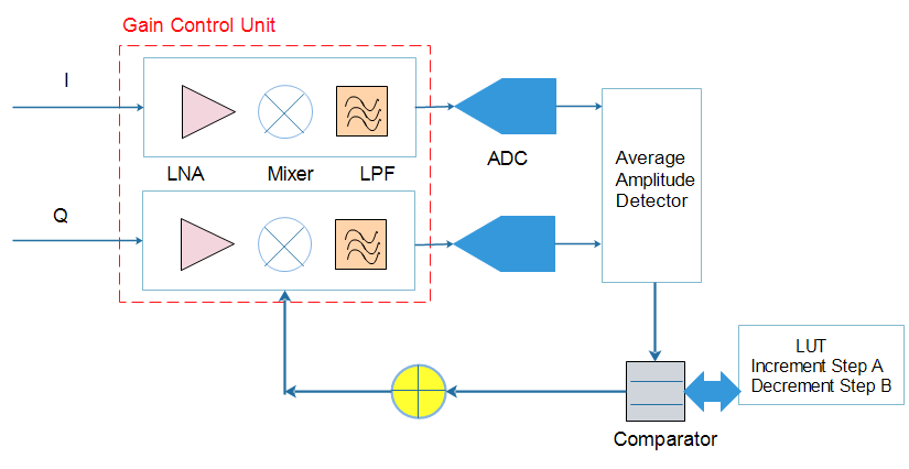
Average Amplitude Estimator:
After ADC operation, the average amplitude of signal is continuously estimated. The average amplitude determines whether the received signal is within the dynamic range of ADC before adjusting the AGC gain
Comparator:
In order to calculate the gain control value, gain step size, the average amplitude is compared to the reference amplitude. There are set of threshold already defined, which tells the maximum and minimum limit of signal amplitude. If signal is outside of any threshold, then there is a need of increase or decrease of gain by a specific step. That gain step sizes are defined in Look up tables (LUT).

Gain Control Unit (GCU):
The GCU is a linear-in-dB gain control circuitry that adjusts the level of incoming signal with AGC gain.
AGC Important parameters
For stable AGC operation, suitable AGC parameters such as the primary gain (or gain in normal operation), power threshold levels, and the step size should be determined. Primary gain is very important parameter for overall receiver performance. A large gain will saturate the ADC and clip the signal and a small gain will cause quantization noise. It has a trade-off between complexity and performance. One another main parameter is SETTLING TIMES, After a gain change, the RFIC must reset overload detectors and power measurement circuits and wait for the receive path to settle before re-enabling detectors and power measurement blocks.
In FDD system, AGC works continuously, because receiver chain is always ON, but TDD system, things are pretty different. There receiver is not always ON, so at one moment of time receiver signal will be present and at other moment, receiver signal will be absent. There are further AGC techniques like Slow Attack AGC, Fast Attack AGC, where signal level threshold limits, gain step sizes are different.
Slow Attack Mode is intended for slowly changing signals such as those found in some FDD applications such as WCDMA and FDD LTE.
Fast Attack Mode is intended for waveforms that “burst” on and off, such as those found in TDD applications or GSM/EDGE FDD applications. The AGC responds very quickly to overloads at the start of a burst so that the AGC can settle to an optimum gain index by the time the data portion of the signal arrives.

