5G NR Interfaces X2/Xn, S1/NG, F1 and E1 Functions
5G RAN and Core Interfaces
In LTE networks, X2 and S1 interface are defined as an interfaces between RAN nodes and between RAN and Core Network. 5G is expect to operate in two modes as non -standalone and standalone mode of operation. For non-stand operation specification defined the extension for S1 and X2 interfaces where as for standalone operation new interfaces are defined.
These new intefaces are listed below:
- Interface between RAN Node as X2/Xn
- Interface between RAN and Core Network as S1/NG
- Interface for Function Split and Open Interface as F1/E1 within RAN Node
- Interface between PHY and Radio as eCPRI
To know more details about 5G NR deployment do read post Deployments Scenarios for 5G NR
Interface between RAN Nodes (X2/Xn)
The X2 interface used between eNBs in LTE is reused between RAN nodes in non-standalone operation (between eNB and en‒gNB and the Xn interface is newly specified between RAN nodes in standalone operation (between ng‒eNB and ng‒eNB/gNB and gNB/ng‒eNB and gNB.If you are not much aware about terms ng‒eNB, gNB and en‒gNB, please read post 5G Network Abbreviations and Terminologies
The extensions of X2 include functions adopting EN-DC and flow control for split bearers for non-standalone operation. The flow control function, which was defined for LTE-DC split bearers in Release 12, is used for appropriately split downlink data when using the radio resources of multi-ple RAN nodes. Although functions and interfaces just for basic flow control were specified for LTE-DC, the information exchanged between RAN nodes is further enhanced to optimize the flow control for non-standalone operation. Although Xn is based on the X2 function, the UE context management function is chiefly enhanced for adopting new QoS flow framework and network slice. The X2 ex-tension functions and the Xn functions are listed below.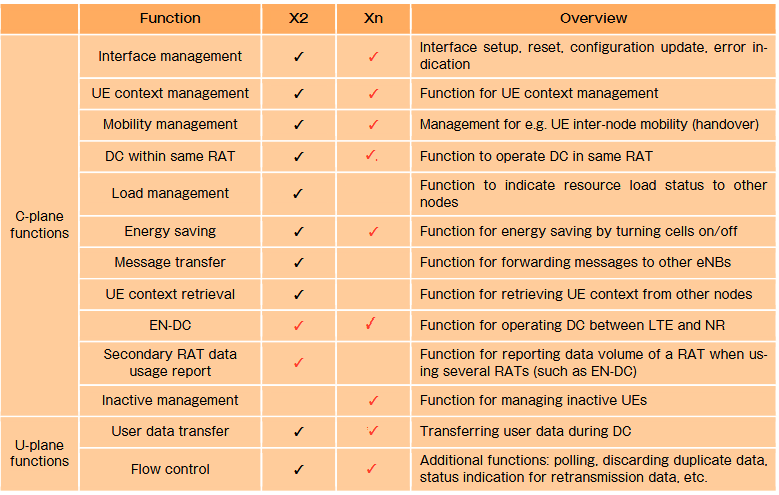
Below is the 3GPP specification list for Xn interface.
- 38.420 TS Xn general aspects and principles
- 38.421 TS Xn layer 1
- 38.422 TS Xn signalling transport
- 38.423 TS Xn Application Protocol (XnAP)
- 38.424 TS Xn data transport
- 38.425 TS Xn interface user plane protocol
Interface between RAN Node and Core Network (S1/N2/NG)
Similar to interface between RAN nodes, the interfaces between RAN nodes and Core network also differ for non-standalone and standalone operation. In non-standalone operation, the S1 interface is reused for between RAN node and EPC. On the other hand a new interface with name NG is specified between RAN nodes (ng‒eNB/gNB and 5GCs in standalone operation.
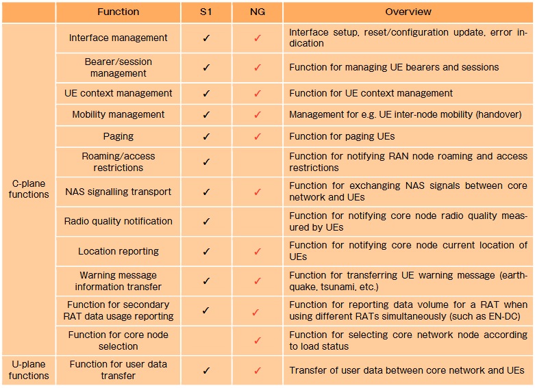
The extensions of S1 include a function that reports data volume for a specific RAT in non-standalone operation. In the standardization discussions, there were demands from operators for charging based on the data volume of each RAT (i.e., LTE and NR) in non-standalone operation. Thus, this function was introduced for calculating the amount of data volume via NR. In non-standalone operation, since the S1‒C interface is only established between the Master Node and Core Network, the data volume through Master Node terminated bearers is counted by the Master Node itself and reported directly to the Core Network via S1, while the data volume from Secondary Node terminated bearers is counted by Secondary Node and reported to Master Node via X2, and then reported by Master Node to Core Node via S1.
Similar with Xn for X2, although NG is based on the S1 function, the bearer/session management functions and UE context management functions have been enhanced for adopting a new QoS framework and network slices. The S1 extension functions and the NG functions are listed below.
Below is the 3GPP specification defined for NG interface.
- 38.410 TS NG general aspects and principles
- 38.411 TS NG layer 1
- 38.412 TS NG signalling transport
- 38.413 TS NG Application Protocol (NGAP)
- 38.414 TS NG data transport
Functional Split and Open Interfaces (F1, E1) within RAN Nodes
In 3GPP standardization, the functional split within a RAN node which places part of the functions in separate logical nodes, and an open interfacing between logical nodes has been discussed. The functional split of gNB and the interfaces between the logical nodes details can be read in following earlier post
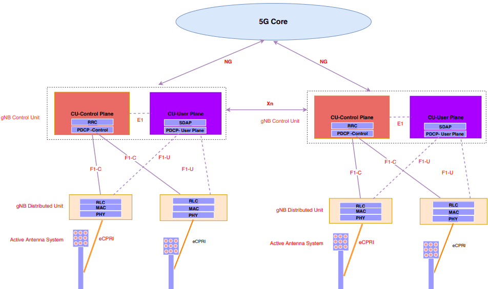
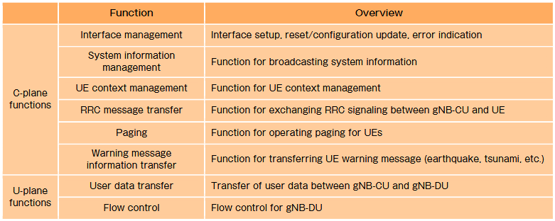
To address the issue of explosive in-creases of the bandwidth required for the transport between the Central Unit (CU) and Distributed Unit (DU) by the introduction of massive MIMO and extending the frequency bandwidth using Cloud RAN (C-RAN) deployment, the new functional split between CU (gNB-CU) and DU (gNB-DU) within gNB and the corresponding open interface between these nodes were defined. Specifically, a functional split was adopted where the PDCP layer and above can be located in the gNB-CU, and the RLC layer and below can be located in the gNB-DU. The standard interface between them is specified as F1. The functions of the F1 interface are listed below.
In addition to the functional split between gNB-CU and gNB-DU, the functional split of C-plane and U-plane in gNB-CU. For example, when the C-plane function can be placed near gNB-DU and the U-plane functions can be placed near Core Network, the RRC signal used by the C-plane can be controlled without long delays and the U-plane functions can be placed in the cloud. Conversely, when the C-plane function is placed near Core Network and the U-plane function is placed near gNB-DU, it is possible to reduce the delays of U-plane signals for edge computing applications, and the C-plane functions can be migrated to the cloud.
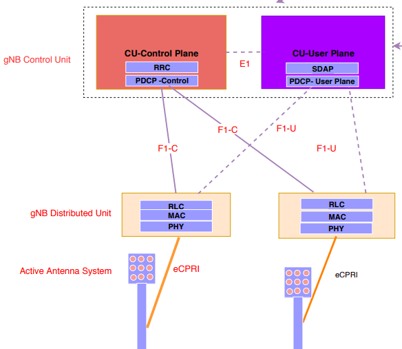
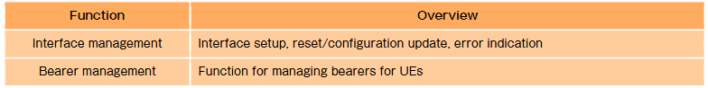
However, with 3GPP standardization, an open interface between the C-plane termination parts and U-plane termination parts of gNB-CU has been specified so that this sort of functional separation can be achieved even between different vendors. A node that terminates the C-plane of gNB-CU is called gNB-CU-CP, and a node that terminates the U-plane of the gNB-CU is called gNB-CU-UP. The standard interface between these nodes is specified as E1. The functions of E1 interface is listed below.
Related Post
- 5G NR gNB Logical Architecture and Its Functional Splits
- 5G NR Interfaces X2/Xn, S1/NG, F1 and E1 Functions
- 5G Channel Modes: Requirements and Deployment Scenarios
- 5G Self Backhaul- Integrated Access and Backhaul
- 5G Transport Network Requirement for Indian Telecom