5G MSG3 – PUSCH Scheduled Transmission by RAR UL grant
Introduction
When we want to connect a UE to 5G network, it has to synchronize in downlink as well as in uplink. Downlink synchronization is obtained after successfully decoding SSB, In order to establish uplink synchronization and RRC connection, UE has to perform RACH random access procedure.
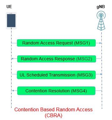
In Contention based, RACH UE does follow four step as shown in below picture and listed below.
- Random Access Preamble Transmission – Msg1
- Random Access Response – Msg2
- Scheduled UL (PUSCH) Transmission – Msg3
- Contention Resolution – Msg4
In this post we will discuss in detail about the Msg3.
The MSG3 is very first PUSCH transmission scheduled by MSG2 with the RAR UL grant. A UL grant includes scheduling information for frequency hopping, frequency and time domain resource allocation, MCS, and transmit power control necessary information required for MSG3.
MSG 3 – Frequency Domain Resource Allocation
An active UL bandwidth part (BWP) is indicated by higher layers for a PUSCH transmission scheduled by a RAR UL grant. For determining the frequency domain resource allocation for the PUSCH transmission within the active UL BWP UE does follow below mentioned steps.
-
- If the active UL BWP and the initial UL BWP have same Sub carrier Spacing and same CP length and the active UL BWP includes all RBs of the initial UL BWP, or the active UL BWP is the initial UL BWP: the initial UL BWP is used,
- Else:
- RB numbering starts from the first Resource Block (RB) of the active UL BWP
- Maximum no. of RBs for frequency domain resource allocation equals the number of RBs in the initial UL BWP
In both cases, despite the start RB may be different, the maximum no. of RBs for frequency domain resource allocation always equals the number of RBs in the initial UL BWP.
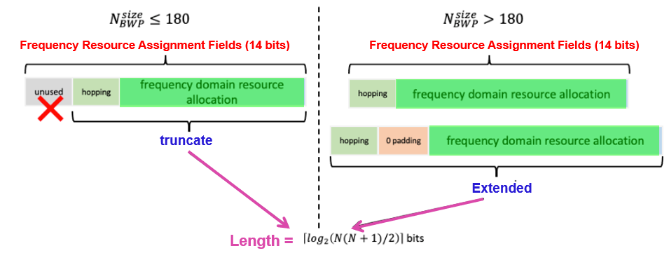
The frequency domain resource allocation is by uplink resource allocation type 1. For an initial UL BWP size of ![]() RBs, a UE processes the frequency domain resource assignment field as follows:
RBs, a UE processes the frequency domain resource assignment field as follows:
- if
 : truncate the frequency domain resource assignment field to its least significant bits. You may have question Why 180 ?
- thus, 14 bits resource allocation can indicate up to 180 RBs
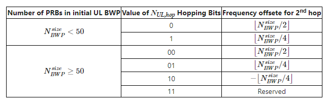
- Else expand the frequency domain resource assignment field by inserting bit(s) of zero after the NUL, hop bits, where NUL, hop is provided in Table below.
- The truncated or expanded frequency resource assignment field is then interpreted as the frequency resource assignment field in DCI format 0_0.
For a PUSCH transmission with frequency hopping scheduled by RAR UL grant or for a Msg3 PUSCH retransmission, the frequency offset for the second hop can be considered from Table below.
MSG 3 – Time Domain Resource Allocation
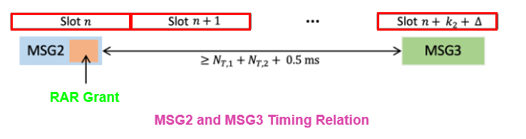
With reference to time slots for a PUSCH transmission scheduled by a RAR UL grant, if a UE receives a PDSCH with a RAR message ending in slot n for a corresponding PRACH transmission from the UE, the UE transmits the PUSCH in slot n + k2 + Δ, where k2 and Δ.
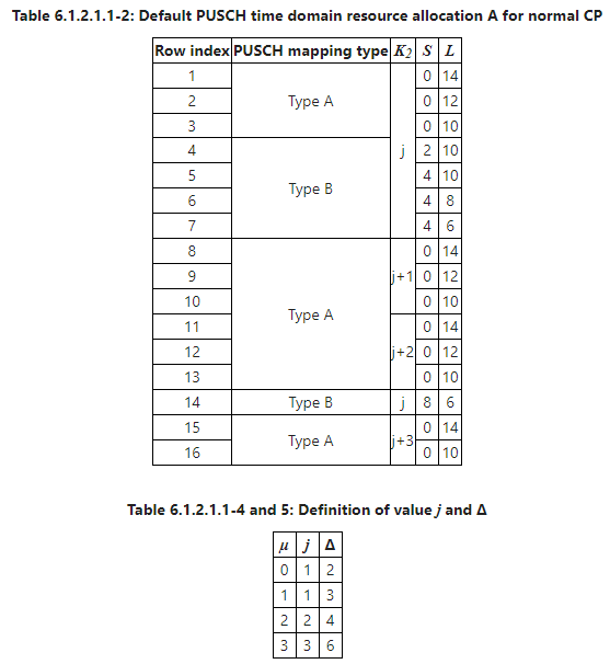
Time resource allocation is a set of 4 bits which represents a index to a PUSCH time domain resource allocation configuration table of up to 16 entries:
- If pusch-ConfigCommon includes pusch-TimeDomainAllocationList then use table defined by pusch-TimeDomainAllocationList, where the possible values of k2 is between 0 and 32.
- Else use the default A table as shown below.
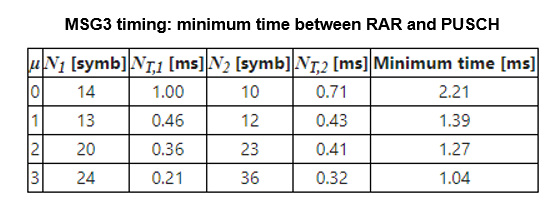
The UE may assume a minimum time between the last symbol of a PDSCH reception conveying a RAR message with a RAR UL grant and the first symbol of a corresponding PUSCH transmission scheduled by the RAR UL grant is equal to NT,1 + NT,2 + 0.5 msec,
where:
- NT,1 is a time duration of N1 symbols corresponding to a PDSCH processing time for UE processing capability 1 when additional PDSCH DM-RS is configured
- for μ = 0, N1,0 = 14
- NT,2 is a time duration of N2 symbols corresponding to a PUSCH preparation time for UE processing capability 1
- N1 and N2 correspond to the smaller of the SCS configurations for the PDSCH and the PUSCH
Other Consideration
- SCS for the PUSCH transmission is provided by subcarrierSpacing in BWP-UplinkCommon
- UE transmits PRACH and the PUSCH on a same uplink carrier of a same serving cell.
- UE transmits a transport block in a PUSCH scheduled by a RAR UL grant in a corresponding RAR message using RV0 redundancy version.
- If a TC-RNTI is provided by higher layers, the scrambling of the PUSCH corresponding to the RAR UL grant is done with TC-RNTI. Otherwise, the scrambling is done with C-RNTI.
- Msg3 PUSCH retransmissions, if any, of the transport block, are scheduled by a DCI format 0_0 with CRC scrambled by a TC-RNTI provided in the corresponding RAR message. The UE always transmits the PUSCH scheduled by a RAR UL grant without repetitions.
- UE determines whether or not to apply transform precoding based on msg3-transformPrecoder in RACH-ConfigCommon
References:
- 3GPP TS 38.211 NR; Physical channels and modulation
- 3GPP TS 38.221 NR; Medium Access Control (MAC) protocol specification
- 3GPP TS 38.300 NR; NR and NG-RAN Overall description; Stage-2
Related Post:
- 5G NR RA-RNTI Calculation
- 5G NR Msg2 Random Access Response (RAR)
- 5G Cloud RAN Fronthaul Architectures
- SSB Based and CSI-RS Based RLM in 5G