What is Active Antenna System (AAS) and its 3D Aspect, Why AAS for 5G ?
An active antenna is an antenna that contains active electronic components like antenna-integrated radio designs place the RF module next to the passive antenna to reduce cable losses.
Active Antenna does not need to be merely passive elements. With intelligent integration, active antenna technology transforms traditional antenna to contribute to base station efficiency. This enables operators to significantly increase the capacity and coverage targets set for their network.
As a base station system evolved, the AAS integrated the active transceiver array and the passive antenna array into one radome.
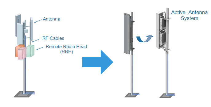
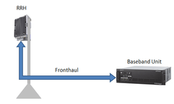
In normal mode, RRH is connected to Antenna through RF cable. So there are two different units (one is RRH and second is antenna) as shown below:

On the other hand, AAS is altogether single unit where different antenna elements has their own RF transceiver chains integrated as shown below:
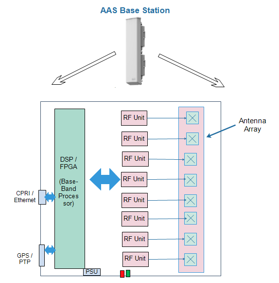
AAS is integrated into the antenna so as to offer possibilities for finer grained digital control of the beamforming weight of each individual subelement within the antenna.
Its 3D-MIMO technologies fully utilize radio resources in both the micro- and macro-spatial domains.
3D Aspect of AAS
Traditionally and still, evaluations in the wireless communication field use channel models with only two dimensions, even though we live in a three-dimensional world. The vertical direction is basically non-existent in these models, all UEs are assumed to be placed on ground-level.
UE specific elevation beamforming is one key technique that we are exploring in the context of 3D channel models. It allows a beam to be directed in a way that suits each individual UE in the cell. For example, a UE high up in a high-rise may desire a beam pointing upwards, while a UE on the ground level may get a downwards pointing beam.

The related MU-MIMO technique can be used to co-schedule UEs that appear in different horizontal and/or elevation angles. Coordinated beamforming may utilize the additional degrees of freedom provided by the elevation domain to more efficiently avoid interference on victim UEs. There are almost endless opportunities in combining the various basic multi-antenna components.
The performance potential of beamforming techniques tends to increase with an increasing number of antennas, since the baseband gets access to more degrees of spatial freedom. This is facilitated by techniques for active antenna systems (AAS) where the radio is integrated into the antenna so as to offer possibilities for finer grained digital control of the beamforming weight of each individual subelement within the antenna.
AAS for 5G
Massive MIMO is the back-bone for 5G network where 100 or more antenna elements are to be used for various benefits. But it is difficult to introduce massive-elements antennas (100 or more elements) that are required for massive MIMO into traditional base stations, attaching over 100 RF cables between each antenna element and RF TRX unit seems unrealistic and adding more RF losses. Using an AAS that combines the antennas, and RF TRX unit (transmitter and receiver chains), into one unit would be an effective way to resolve these issues.
In addition to the conventional roof top mounting locations, small cells are expected to cover shopping malls, Stadiums, food canteens, or different premises. To be effective, AAS/MIMO must be able to flexibly adapt to each individual small cell user’s distribution environment, so optimum antenna structure can be offered for any individual situation in terms of the number of vertical and horizontal antenna elements and the number of independent transceivers, adding huge efficiency to the network.
AAS BENEFITS
- There is a potential to significantly reduce the site footprint
- The distribution of radio functions within the antenna results in built-in redundancy and improved thermal performance, which can result in higher system availability (lower failure rates).
- Distributed transceivers can support a host of advanced electronic beam-tilt features that can enable improvements in network capacity and coverage
- Integrating the active transceiver array and the passive antenna array into one radome reduces cable losses
Related Posts:
- Smart Antennas and Beamforming, Understanding with GNU : Part 1
- Smart Antennas and Beamforming, Understanding with GNU : Part 2
- Smart Antennas and Beamforming, Understanding with GNU : Part 3