Smart Antennas and Beamforming, Understanding with GNU : Part 1
Introduction and Definitions:
LTE transmission mode 7,8 and 9 defines fixed precoder based beamforming and adaptive precoder based beamforming. Main advantage of beamforming and smart antenna system is that by using focused beam, interference can be reduced and wanted signal can be effectively steered towards specific user. This technology becomes even more useful in dense urban environment.
This article talks about basics of antenna radiation patterns, beamforming and smart antenna adaptive beamforming concepts.
Before going into details lets agree on some definitions.
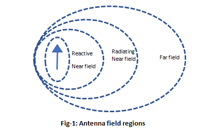
Antenna Field Regions:
Electromagnetic field that is produced by antenna can be broadly divided into four regions.
- Antenna region: This is physical boundary of antenna.
- Reactive near field region: This is the region where reactive energy lies surrounding the antenna.
- Radiating near field region: This is the region where antenna filed radiates. Here radiation pattern changes with distance. It is in between Reactive near field and far field.
- Far field region: This region is far beyond the radiating near filed and radiation pattern does not change with distance.
 Antenna Radiation Patterns:
Radiation patterns define the directional property of the antenna and are usually represented in form of function or plot. This plot or function defines the variation of power radiated by an antenna in the direction away from the antenna.
GNU Octave Script to Generate Antenna Radiation Pattern:
Let’s plot radiation pattern of an antenna using a simple octave script. Script and its output is given below:
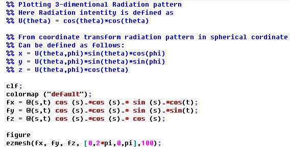
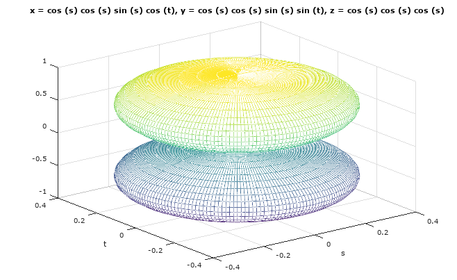 Fig-2: 3-D Radiation pattern plot from octave script
Beamforming and Phased Array Antenna:
It can be seen from the above plot that radiation pattern consists of a beam like pattern. Further, It can be derived that the beam width of far field radiation pattern of an antenna in a particular direction is inversely proportional to the corresponding antenna dimension. A tall antenna, for example, will tend to have narrow beam width. So, if we want to direct antenna radiation pattern towards any specific user we would need a tall antenna and a mechanism to steer it towards specific user. Obviously, this is impractical.
Another relatively better approach is based on phased array antenna. Idea is that when the same signal is transmitted from multiple antenna elements, they constructively or destructively add up. This makes a narrow beam at the output in the perpendicular direction of the antenna elements.
Moreover, if a time delay is added to each of the signals that is sent out from each antenna element then the direction of the narrow beam changes. And, the direction of the beam depends on how much time delay is added to signal from each antenna element. Introducing a time delay is trivial and by doing this narrow beam can be directed towards a specific user without manually steering the antenna.
Another thing to note here is that as the number of antenna elements are increased beam also becomes narrower. So, by adding more antenna elements beam can be made more focused toward a specific user.
Let’s understand this concept using a simple Octave script given below:
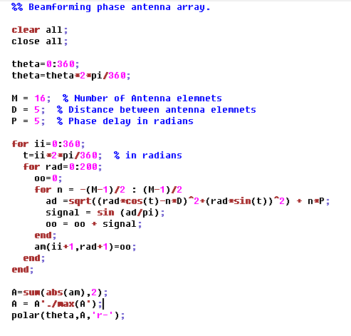
The output of this script for varying number of antenna element and phase delay is given below:
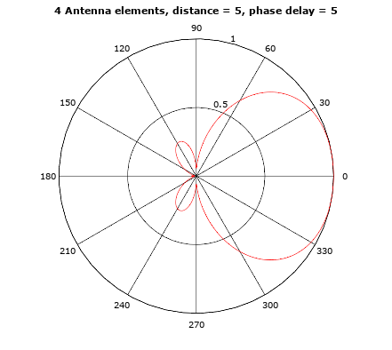
Fig-3 a: Antenna beam pattern with M =4, D =5 and P =5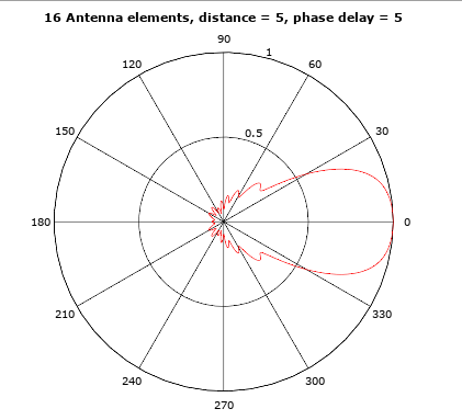
Fig-3 b: Antenna beam pattern with M =16, D =5 and P =5

Fig-3 c: Antenna beam pattern with M =16, D =5 and P =40
From figure 3a,3b and 3c, the following can be concluded:
- More number of antenna elements, narrower the beam pattern.
- Change in phase delay results in a change in direction of the beam.
Smart antenna and adaptive beamforming:
Although above approach is good but not smart enough. It does not use any information from the transmission channel to adapt beamforming. This is where Smart antenna comes into the picture. Smart antennae are adaptive antenna arrays. It utilizes digital signal processing techniques to produce a spatial orientation of the beam. These DSP techniques also utilize channel state information so that interference signal can be suppressed and a useful signal can be effectively steered towards intended user.
DOA (direction of arrival) estimation is one of the main functional requirements for direction-finding smart antennas in future generation mobile and stealthy communications systems.
Part-2 will discuss DOA estimation techniques and its use in adaptive beamforming.
Smart Antennas and Beamforming, Understanding with GNU : Part 2
Article Submitted By Mr. Dheeraj Sharma

Dheeraj Sharma is working as LTE-A/5G Physical Layer ( DSP) Engineer. He has expertise in DSP/Physical layer firmware development, Integration and optimization in multiple Radio Access Technologies (GSM/GPRS/EDGE, GMR-1 3G, LTE,xDSL)


