Open Midhaul F1 Interface F1-C and F1-U
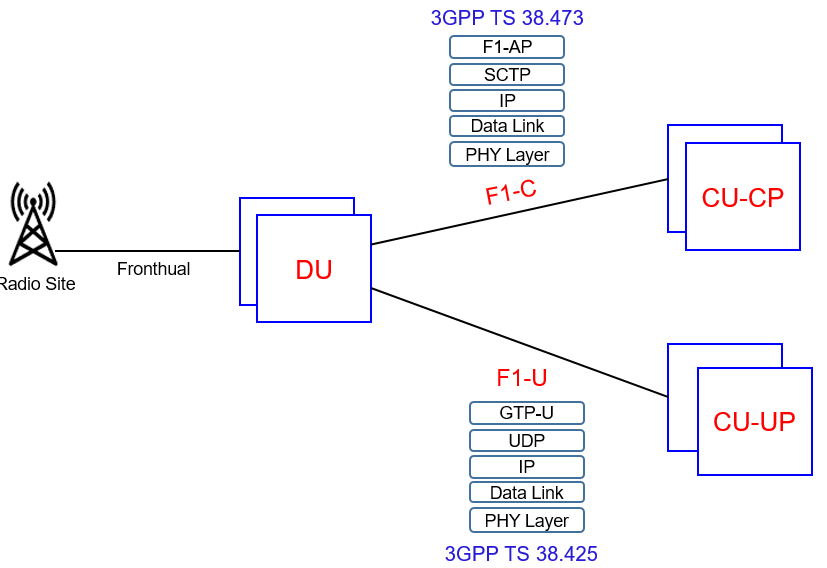
The F1 interface connects a gNB CU to a gNB DU. This interface is applicable to the CU-DU Split gNB architecture. The control plane of the F1 (F 1-C) allows signaling between the CU and DU, while the user plane of the F1 (F 1-U) allows the transfer of application data.
Following figure illustrates the CP and UP protocol stacks belonging to the F1 interface. The C-plane uses SCTP over IP, whereas the U-plane uses GTP-U over UDP over IP for transport layer.
F1 Interface Characteristics:
- F1 interface is an open interface i.e. the end point can be from different vendors
- F1 general aspects and principles is given in 3GPP TS 38.470, F1AP in 3GPP TS 38.473 and F1-U within 3GPP TS 38.425
- F1 interface supports the exchange of signaling and data information between the endpoints
- Logical standpoint, the F1 is a point-to-point interface between the endpoints means a point-to-point logical interface should be feasible even in the absence of a physical direct connection between the endpoints
- F1 interface supports control plane and user plane separation
- F1 interface separates Radio Network Layer and Transport Network Layer
- F1 interface enables exchange of UE associated information and non-UE associated information
- One gNB-CU and a set of gNB-DUs form a logical gNB node
- gNB-CU can also be separated in control plane and user plane
F1 Interface Functionalities
F1 Interface performs following management operations.
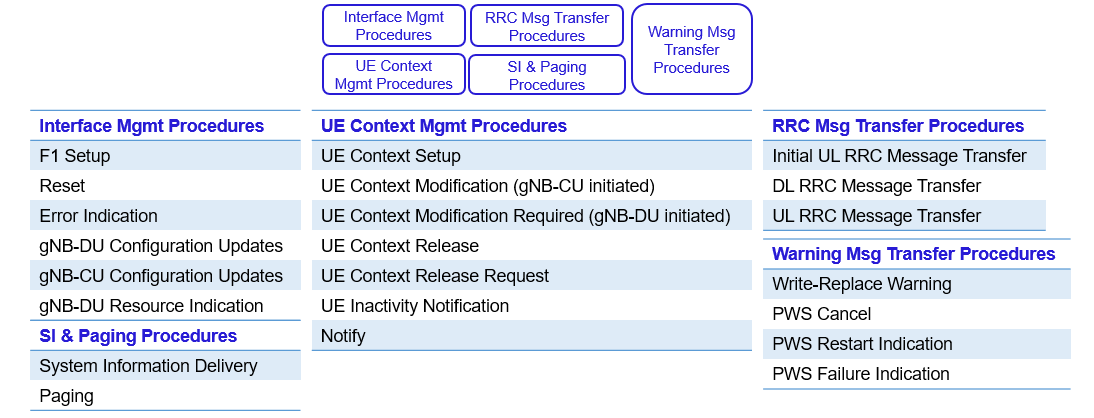
Control Plane Functionalities:
- F1 Setup: The F1 Setup procedure is used to create a logical F1 connection between the CU-CP and DU. It is necessary to establish an SCTP connection between the CU-CP and DU before the F1 Setup procedure can be initiated. The DU initiates the procedure by sending an F1 Setup Request message, while the CU-CP completes the procedure by returning an F1 Setup Response. The F1 Setup Request is used to inform the CU-CP about DU identity and the set of cells supported by the DU. The F1 Setup Response is used to indicate which DU cells should be activated.
- Reset: The Reset procedure can be initiated by either the CU-CP or DU. It is used to reset either all F1AP UE contexts, or a specific subset of F1 AP UE contexts. When the reset is initiated by the CU-CP, the DU releases all relevant resources on the F1 interface and all relevant radio resources. When the reset is initiated by the DU, the CU-CP releases all relevant resources on the F1 interface. The
procedure uses the Reset/Reset Acknowledge handshake. It does not cause the F1 interface itself to reset. - Error Indication: This procedure can be initiated by either the CU-CP or DU. It is used to report that an error has been detected within an incoming F1 AP message. It is applicable when the error cannot be reported using a failure message belonging to the relevant signaling procedure. The procedure uses only the Error Indication message.
- gNB-DU Configuration Update: It is used by the DU to provide the CU-CP updated information regarding its set of supported cells. The GNB-DU Configuration Update message allows new cells to be added, existing cells to be modified, or existing cells to be deleted. The CU-CP acknowledges the update using the GNB-DU Configuration Update Acknowledge message
- gNB-CU Configuration Update: It is used by the CU to provide the DU with updated information regarding the set of cells to be activated or deactivated. The CU is able to specify the PCI to be used when activating a cell. The CU initiates the procedure using the GNB-CU Configuration Update message, whereas the DU acknowledges the update using the GNB-CU Configuration Update Acknowledge message.
- gNB-DU Resource Coordination: This procedure is applicable when a gNB and a ng-eNB share spectrum with overlapping coverage areas. The F1AP procedure used as part of the corresponding XnAP procedure, i.e. the F1 AP procedure is used to relay the XnAP messages between the CU and DU. The F1AP: GNB-DU Resource Coordination Request message is used to encapsulate the XnAP: E-UTRA – NR Cell Resource Coordination Request message. Similarly, the F1AP response encapsulates the XnAP response. The DU is the target for this procedure rather than the CU because it impacts the Packet Scheduler which is located within the DU.
- gNB-DU Status Indication: The DU can use the gNB-DU Status Indication procedure to infom1 the CU that it is overloaded. The gNB-DU Status Indication message simply includes a flag to indicate whether or not the DU is overloaded.
- Initial UL RRC Message Transfer: It is used to forward the initial uplink RRC message from the DU to the CU-CP. This initial uplink message belongs to the CCCH, e.g. an RRC Setup Request message. The procedure is also used to inform the CU-CP of the C-RNTI which has been allocated by the DU, and to provide the CU-CP with the CellGroupConfig parameter structure which includes information regarding the RLC, MAC and Physical Layer configurations for the new connection. In addition, the procedure is used to initiate the establishment of a UE-associated connection across the F 1 interface. This is done by providing the CU-CP with a ‘gNB-DU UE F1AP Identity‘ which can be used to address the UE-associated connection during any subsequent message transfer. The CU-CP provides a corresponding ‘gNB-CU UE F1AP Identity‘ within the first DL RRC Message Transfer.
- DL RRC Message Transfer: It is used to transfer downlink RRC messages from the CU-CP to the DU. The CU-CP generates the RRC messages and processes them within the PDCP layer. They are then transferred to the DU as PDCP PDU. The DL RRC Message Transfer message can include a flag which instructs the DU to apply SRB duplication. This is applicable when the connection bas been configured with duplication across multiple NR carriers. Duplication improves reliability by transmitting the same RRC message using multiple carriers. ln addition, the DL RRC Message Transfer message can include a RAT-Frequency Priority information clement to support prioritization decisions within the DU when transmitting the RRC message.
- UL RRC Message Transfer: procedure is used to transfer uplink RRC messages from the DU to the CU. The DU receives RRC messages from the UE and processes them within the Physical, MAC and RLC layers. They arc then transferred to the CU as PDCP
PDU - UE Context Setup: F1AP UE Context Setup procedure includes UE Context Setup Request/ UE Context Setup Response handshake. This procedure is always initiated by the CU-CP. In the case of initial connection setup. the F1AP: UE Context Setup Request follows the NG-C: Initial UE Context Setup Request from the AMF. The F1AP: UE Context Setup Request message can be used to configure a set of SRB and a set of DRB. The DU is provided with an uplink GTP-U TEID for each DRB to allow the transfer of uplink user plane data towards the CU. The F1AP: UE Context Setup Response message specifics the corresponding downlink GTP-U TEID. UE Context Setup procedure can also be used during incoming handover procedures, i.e. to create a new UE context at the target DU. The CU requests a new UE context at the target DU immediately after the handover decision, i.e. after receiving the RRC: Measurement Report from the UE.
- UE Context Modification: CU-CP uses the UE Context Modification procedure to update the configuration provided during Initial UE Context Setup. It can also be used to instruct the DU to stop or re-start transmission towards the UE. The UE Context Modification Request can be used to encapsulate an RRC message which the DU subsequently transmits to the UE. DU transmits an RRC Reconfiguration after receiving it from the CU within a UE Context Modification Request. The DU uses the UE Context Modification Required procedure to update the set of downlink GTP-U TEID. It can also specify a requirement to release specific SRB and DRB. In addition, it can provide updated information regarding its cells and it can specify a requirement to update the resource co-ordination information which is applicable when a gNB and a ng-eNB share spectrum with overlapping coverage.
- UE Context Release: An existing UE context can be released by the CU-CP using the UE Context Release procedure. This procedure uses the UE Context Release Command/UE Context Release Complete handshake. The DU is able to request that the CU initiates this procedure by sending a UE Context Release Request message and sending this message corresponds to the UE Context Release Request procedure.
- UE Inactivity Notification: The procedure allows the DU to report the inactivity status of a UE. DU indicates either ‘Active or ‘Not Active’ for each individual DRB
- Notify: Notify procedure allows the DU to inform the CU-CP when a specific DRB no longer satisfies its Guaranteed Flow Bit Rate (GFBR). This is applicable to GBR QoS Flows which have Notification Control enabled. The DU is also able to inform the CU if GFBR is subsequently fulfilled again
- System Information Delivery: This procedure allows the CU-CP to provide the DU with a list of ‘Other System Information’ (OSI) types to be broadcast across a specific cell. OSI includes SIB2 to SIB9. The System Information Delivery procedure can be triggered by a UE request for the broadcast of Other System Information
- Write-Replace Warning: This procedure allows the CU to initiate or to overwrite the broadcast of warning messages. These messages are applicable to a Public Warning System (PWS). The procedure uses the Write-Replace Warning Request/Write-Replace Warning Response handshake between the CU-CP and DU. The Write-Replace Warning Request message includes the PWS System Information to be broadcast. The CU-CP can use the PWS Cancel procedure to instruct a DU to stop broadcasting PWS System Information. The DU uses the PWS Restart Indication procedure to provide a list of cells to the CU which have PWS information available. The DU uses the PWS Failure Indication procedure to provide a list of cells to the CU where PWS transmission has failed
- Paging: The CU-CP uses the Paging procedure when requesting the DU to page a specific UE. The Paging message includes the UE Identity Index which can be used to calculate the Paging Frame for the target UE. Paging message also includes either a RAN UE Paging Identity (I-RNTI) or a Core Network UE Paging Identity (S-TMSI). An I-RNTI is allocated to a UE when using the RRC Inactive state. The DU is also provided with the paging DRX cycle length, the paging priority and the list of cells which arc required to transmit the paging message
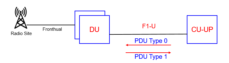
User Plane Functionality:
- The user plane of the F1-U transfers application data between CU-UP and DU. GTP-U tunnels are used to transfer the application data. These tunnels are identified using their TEID. A tunnel is setup for each DRB. The user plane protocol which runs above the GTP-U layer provides various control mechanisms associated with the transfer of downlink data. These control mechanisms include flow control, packet loss detection and successful delivery reporting. The frame formats used by the user plane protocol is referred as PDU Type 0 is sent by the CU, whereas PDU Type 1 is sent by the DU.
-
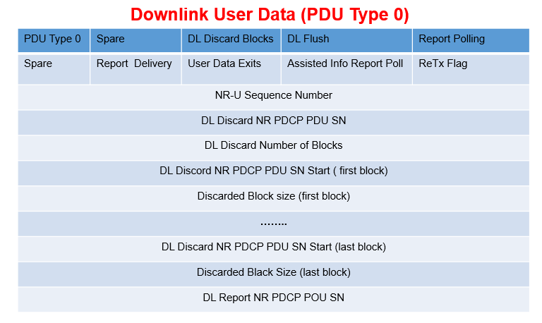
- PDU Type 0: The CU-UP uses PDU Type O to add a sequence number to each downlink data packet. The DU uses this sequence number to detect lost packets. The CU-CP can also use POU Type Oto provide various discard instructions. If the DU reports Radio link outage then the CU-UP may attempt re-transmission from the PDCP layer using a second DU. If the second DU reports successful delivery of the PDCP PDU, the CU-UP instructs the original DU to discard the successfully delivered packets to avoid unnecessary transmission
-
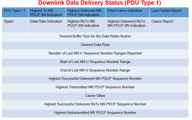
- PDU Type 1: The DU uses PDU Type 1 to report any lost packets and also to control the rate at which downlink data is sent by the CU, i.e. it provides a mechanism for flow control to avoid the buffers within the DU becoming too full. The DU signals the sequence number of the highest successfully delivered PDCP PDU, the desired buffer level and the desired data rate. The desired data rate is specified as the number of bytes which the DU would like to receive within a 1 second time interval. The CU uses these information elements to determine the quantity of data to forward towards the DU. The DU can also use PDU Type 1 to indicate ‘Radio Link Outage’ or ‘Radio Link Resume’.
Reference:
- 3GPP TS 38.470 5G NG-RAN F1 general aspects and principles
- 3GPP TS 38.473 5G; NG-RAN; F1 Application Protocol (F1AP)
- 3GPP TS 38.425 5G; NG-RAN; NR user plane protocol
Related Post:
- 5G NR gNB Logical Architecture and Its Functional Splits
- 5G NR gNB High Layer Split
- 5G NR Interfaces X2/Xn, S1/NG, F1 and E1 Functions
- 5G Channel Modes: Requirements and Deployment Scenarios
- 5G Self Backhaul- Integrated Access and Backhaul
- 5G NR Radio Protocol Stack (Layer 2 and Layer 3)


