5G QoS Architecture, QoS Attribute and QoS Flow
5G QoS Introduction
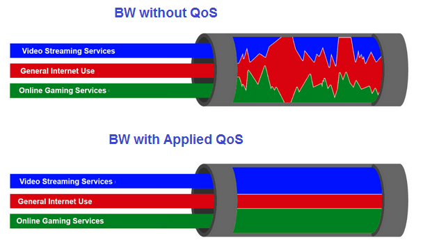
Quality of service (QoS) refer to the measurement of the overall performance of a service experienced by the users of the network. To quantitatively measure the QoS packet loss, bit rate, throughput, transmission delay, availability, jitter, etc. related aspects of service are considered. Following figure show the performance of channel Bandwidth (BW) with and without QoS.
Some Popular Definitions for QoS
- As per ITU definition, QoS comprises requirements on all the aspects of a connection, such as service response time, loss, signal-to-noise ratio, crosstalk, echo, interrupts, frequency response, loudness levels
- Quality of service can be defined as the ability to provide different priority to different applications, users, or data flows, or to guarantee a certain level of performance to a data flow
- QoS can be defined as a control mechanisms is to provide high quality communication over a best-effort network by over-provisioning the capacity so that it is sufficient for the expected peak traffic load
- QoS sometimes refers to the level of quality of service, i.e. the guaranteed service quality
- QoS can be also be defined as acceptable cumulative effect on subscriber satisfaction of all imperfections affecting the service
- QoS can also be defined as a network protocol that enables a traffic contract with the application software and reserve capacity in the network nodes
5G QoS Architecture
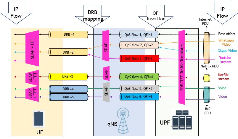
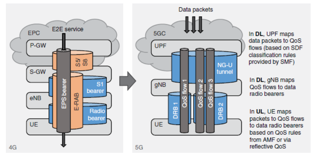
In 5G NR, QoS is enforced at the QoS flow level. Each QoS flow packets are classified and marked using QoS Flow Identifier (QFI). The 5G QoS flows are mapped in the Access Network to DRBs (Data Radio Bearers) unlike in 4G where mapping is one to one between EPC and Radio Bearers. 5G QoS architecture supports following QoS flow types.
-
- GBR QoS flow which requires guaranteed flow bit rate
- Non-GBR QoS flow which does not require guaranteed flow bit rate
- Delay Critical QoS flow, For Mission Critical guaranteed flow bit rate
The QoS architecture in 5G, 5G RAN is connected to 5G Core as it is depicted in following figure. Here we can see followings:
- 5G Core establishes one or more PDU Sessions for each UEs
- 5G-RAN establishes at least one Data Radio Bearers (DRB) together with the PDU Session and additional DRB(s) for QoS flow(s) of that PDU session can be subsequently configured for each UEs
- 5G-RAN maps packets belonging to different PDU sessions to different DRBs
- NAS level packet filters in the UE and in the 5GC associate UL and DL packets with QoS Flows
- AS level mapping rules in the UE and in the 5G-RAN associate UL and DL QoS Flows with DRBs
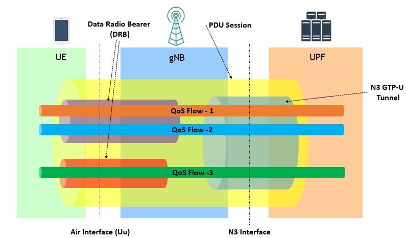
5G-RAN and 5G-Core ensure quality of service (e.g. reliability and target delay) by mapping packets to appropriate QoS Flows and DRBs. Hence there is a 2-step mapping of IP-flows to QoS flows (NAS) and from QoS flows to DRBs (Access Stratum).

5G QoS Parameters and Attribute
QoS flow is identified by QFI within PDU session. This QFI is carried in an encapsulation header over N3. For each UE, 5GC establishes one or more PDU sessions and 5G-RAN establishes at least one DRB together with PDU session. Additional DRBs are configured for QoS flows of that PDU session consecutively. 5G-RAN maps packets which belong to the different PDU sessions to different DRBs.
- NAS level, a QoS flow is characterized by a QoS profile provided by 5GC to 5G-RAN and QoS rule(s) provided by 5GC to the UE. A QoS flow may either be GBR or Non-GBR depending on its profile.
-
- The QoS profile is used by gNB to determine the treatment on the radio interface
- QoS rules dictates the mapping between uplink User Plane traffic and QoS flows to the UE.
-
- Access Stratum level, the data radio bearer (DRB) defines the packet treatment on the radio interface (Uu). A DRB serves packets with the same packet forwarding treatment.
-
- The QoS flow to DRB mapping by gNB is based on QFI and the associated QoS profiles (i.e. QoS parameters and QoS characteristics).
- Separate DRBs may be established for QoS flows requiring different packet forwarding treatment, or several QoS Flows belonging to the same PDU session can be multiplexed in the same DRB.
-
5G QoS Flow Descriptions
5G Network can provide the UE, one or more QoS flow descriptions associated with a PDU session during the PDU session establishment or at the PDU session modification. Each QoS flow contains following details:
- A 5G QoS Identifier (5QI)
- An Allocation and Retention Priority (ARP)
- In case of a GBR QoS Flow
- Guaranteed Flow Bit Rate (GFBR) for both uplink and downlink;
- Maximum Flow Bit Rate (MFBR) for both uplink and downlink;
- Maximum Packet Loss Rate for both uplink and downlink;
- Delay Critical Resource Type;
- Notification Control.
- In case of Non-GBR QoS Flow
- Reflective QoS Attribute (RQA)
- Session-AMBR
- UE-AMBR
5G QoS Flow Characteristics
5G QoS characteristics describe the packet forwarding treatment that a QoS Flow receives edge-to-edge between the UE and the UPF in terms of the following performance characteristics:
- Resource Type (GBR, Delay critical GBR or Non-GBR)
- Priority Level
- Packet Delay Budget
- Packet Error Rate
- Averaging window (for GBR and Delay-critical GBR resource type only)
- Maximum Data Burst Volume (for Delay-critical GBR resource type only)
The 5G QoS characteristics should be understood as guidelines for setting node specific parameters for each QoS Flow e.g. for 3GPP radio access link layer protocol configurations. Standardized or pre-configured 5G QoS characteristics, are indicated through the 5QI value, and are not signalled on any interface, unless certain 5G QoS characteristics are modified.
5G QoS Flow to DRB Mapping
In legacy 4G network, the DRB, EPS Bearer, S1 GTP-U and S5-U tunnel has a one-to-one mapping, but in the 5GC, there is only a single user plane network function the UPF for transport of data between the gNB and the core so following mapping is opted.
- DRBs on air interface can have One-to-many relationship with the GTP-U tunnel on N3 interface at UPF.
- Each QoS flow is mapped to a single GTP-U tunnel at N3 interface
- gNB may map individual QoS flows to one more DRBs
- A PDU session may contain multiple QoS flows and several DRBs but only a single N3 GTP-U tunnel.
- A DRB may transport one or more QoS flows.
- The QFI that identifies the flow is carried in an extension header on N3 in the GTP-U protocol, using DL and UL PDU session information frames
- The DL and UL PDU session information frame includes a QoS Flow Identifier (QFI) field for each packet.
- The DL PDU session information frame includes the Reflective QoS Indicator (RQI) field to indicate whether the user plane reflective QoS is to be activated or not. This is only applicable if reflective QoS is activated.
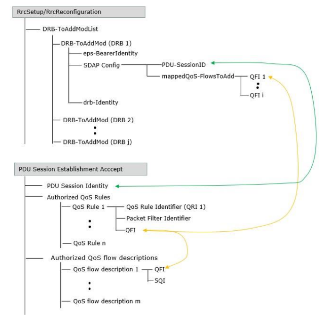
5G QoS Mapping in Signaling
Following picture shows the message structure for RRC Reconfiguration and PDU Session Establishment Accept related to DRB to PDU and PDU to QoS mapping.
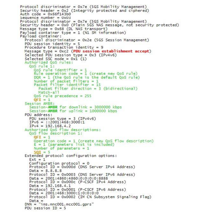
Sample Test Log
What is Reflective QoS?
For UL packet classification, SMF provides QoS rules to the UE or the UE implicitly derives the rules from downlink packets. This mechanism is called Reflective QoS. Both reflective and non-reflective QoS can coexist within the same PDU session.
- Reflective QoS applies to IP PDU session and Ethernet PDU session
- UE indicates to SMF if it supports Reflective QoS during PDU Session Establishment
- UE may change its support and indicate this via PDU Session Modification.
- UE-derived QoS rule would include UL packet filter, QFI and precedence value.
Reflective QoS is controlled per packet. SMF signals the use of Reflective QoS Indication (RQI) marking to UPF. SMF signals Reflective QoS Attribute (RQA) to the gNB via N2 interface. Subsequently, UPF includes RQI for every DL packet of an SDF that’s using Reflective QoS. gNB indicates the RQI to the UE.
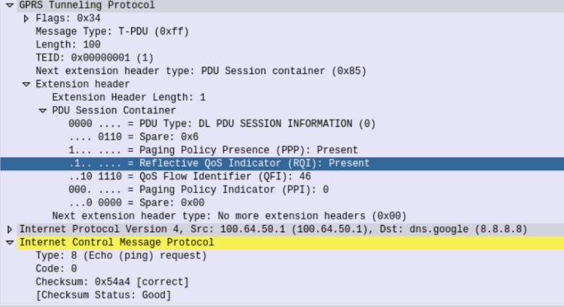
When UE receives a DL packet with RQI, it creates or updates the QoS rule for UL traffic. It also starts the Reflective QoS Timer. There’s one timer per UE-derived rule. The timer is restarted when a matching DL packet is received. Rule is discarded when timer expires.
5G and 4G QoS Parameters Comparison
Below picture and table shows a high level different regarding 5G and 4G QoS Parameters. 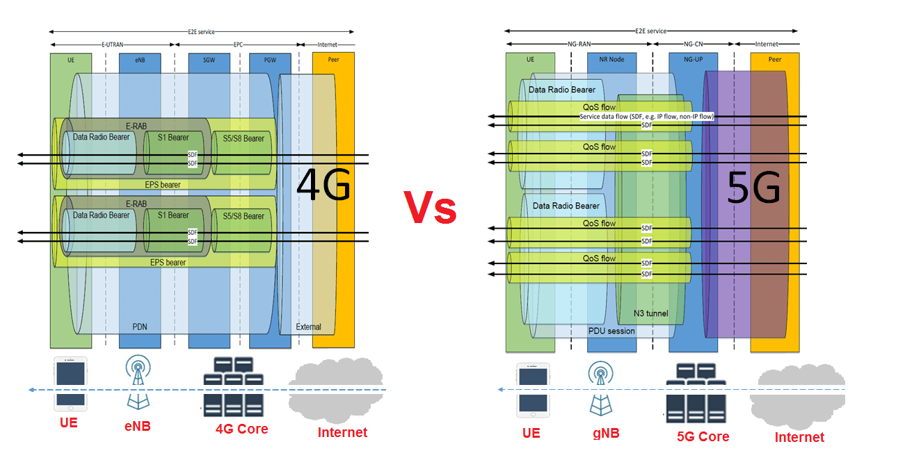
| Parameter | 5G | 4G |
|---|---|---|
| QoS Identifier | 5G QI (QoS Identifier) | QCI (QoS Class Identifier) |
| IP Data Flow | QoS Flow | EPC Bearer |
| Flow/Bearer Identifier | QFI (QoS Flow Identifier) | EBI (EPS Bearer ID) |
| Reflective QoS | RQI (Reflective QoS ID) | Not Applicable |
| Data Session | PDU Session | PDN Connecion |
Reference:
- 3GPP TS 23.501; System architecture for the 5G System (5GS)
Related Posts:
- 5G NG Identities (UE and Network Identifiers)
- 5G NR Radio Protocol Stack (Layer 2 and Layer 3)
- 5G NR User Plane Protocol
- 5G NR QoS Parameters
- 5G NR QoS characteristics

