

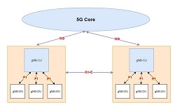
The NG-RAN architecture with a split gNB function is shown in Figure below. Here in NG-RAN a set of gNBs is connected to the 5G Core Network (5GC) through the NG interface, and they can be interconnected through the Xn interface.
A gNB may consist of a gNB-Control Unit (CU) and one or more gNB-Distributed Units (DUs), and the interface between gNB-CU and gNB-DU is called F1. The NG and Xn-C interfaces for a gNB terminate in the gNB-CU. The maximum number of gNB-DUs connected to a gNB-CU is only limited by implementation. As per 3GPP specifications one gNB-DU connects to only one gNB-CU, but implementations that allow multiple gNB-CUs to connect to a single gNB-DU e.g. for added resiliency, are not precluded. One gNB-DU may support one or more cells (sector). The internal structure of the gNB is not visible to the core network and other RAN nodes, so the gNB-CU and connected gNB-DUs are only visible to other gNBs and the 5GC as a gNB.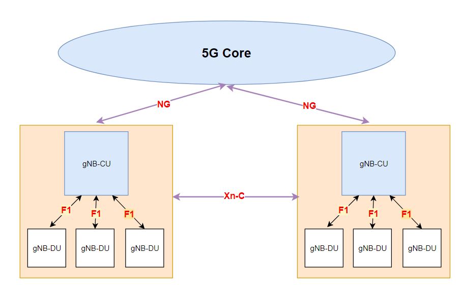

The F1 interface supports signaling exchange and data transmission between the endpoints, separates Radio Network Layer and Transport Network Layer, and enables the exchange of UE-associated and non-UE-associated signaling.
Further F1 interface functions are divided into F1-Control Function (F1-C) and F1-User Function (F1-U).
F1-Control Plane (F1-C) Operations:
- F1 Interface Management Functions: It is consist of F1 setup, gNB-CU Configuration Update, gNB-DU Configuration Update, error indication and reset function.
- System Information Management Functions: The gNB-DU is responsible for the scheduling and broadcasting of system information. For system information broadcasting, the encoding of NR-MIB and SIB1 is performed by the gNB-DU, while the encoding of other SI messages is performed by the gNB-CU. The F1 interface also provides signaling support for on-demand SI delivery, enabling UE energy saving.
- F1 UE Context Management Functions: These functions are responsible for the establishment and modification of the necessary UE context. The establishment of the F1 UE context is initiated by the gNB-CU, and the gNB-DU can accept or reject the establishment based on admission control criteria (e.g., the gNB-DU can reject a context setup or modification request in case resources are not available). In addition, an F1 UE context modification request can be initiated by either gNB-CU or gNB-DU. The receiving node may accept or reject the modification. The F1 UE context management function can be also used to establish, modify and release Data Radio Bearers (DRBs) and Signaling Radio Bearers (SRBs).
- RRC Message Transfer Function: This function is responsible for the transferring of RRC messages from the gNB-CU to the gNB-DU, and vice versa.
F1-U (User Plane) Functions:
- Transfer of User Data: This function allows to transfer user data between gNB-CU and gNB-DU.
- Flow Control Function: This function allows to control the downlink user data transmission towards the gNB-DU. Several functionalities are introduced for improved performance on data transmission, like fast re-transmission of PDCP PDUs lost due to radio link outage, discarding redundant PDUs, the re-transmitted data indication, and the status report.
Mobility Support Requirements:
The following connected-mode mobility scenarios supported is required from CU-DU split.
- Inter-gNB-DU Mobility: The UE moves from one gNB-DU to another within the same gNB-CU.
- Intra-gNB-DU inter-cell mobility: TheUE moves from one cell to another within the same gNB-DU, supported by UE Context Modification (gNB CU initiated) procedure.
- EN-DC Mobility with Inter-gNB-DU Mobility using MCG SRB: The UE moves from one gNB-DU to another within the same gNB-CU when only MCG SRB is available during EN-DC operation.
- EN-DC Mobility with Inter-gNB-DU Mobility using SCG SRB: The UE moves from one gNB-DU to another when SCG SRB is available during EN-DC operation.
Control and User Plane Seperation with Higher Layer Split (HLS)
To optimize the location of different RAN functions according to different scenarios and performance requirements, the gNB-CU can be further separated into its CP and UP parts (the gNB-CU-CP and gNB-CU-UP, respectively).The interface between CU-CP and CU-UP is called E1 which purely a control plane interface. The overall RAN architecture with CU-CP and CU-UP separation is shown in figure below.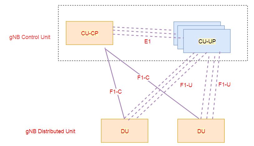

The gNB-CU-CP hosts the RRC and the control plane part of the PDCP protocol; it also terminates the E1 interface connected with the gNB-CU-UP and the F1-C interface connected with the gNB-DU. The gNB-CU-CP hosts the user plane part of the PDCP protocol of the gNB-CU for an en-gNB, and the user plane part of the PDCP protocol and the SDAP protocol of the gNB-CU for a gNB.
The gNB-CU-UP terminates the E1 interface connected with the gNB-CU-CP and the F1-U interface connected with the gNB-DU. A gNB may consist of a gNB-CU-CP, multiple gNB-CU-UPs, and multiple gNB-DUs. The gNB-CU-CPis connected to the gNB-DU through the F1-C interface, and gNB-CU-UP is connected to the gNB-DU through the F1-U interface. One gNB-CU-UP is connected to only one gNB-CU-CP, but implementations allowing a gNB-CU-UP to connect to multiple gNB-CU-CPs e.g. for added resiliency, are not precluded. One gNB-DU can be connected to multiple gNB-CU-UPs under the control of the same gNB-CU-CP. One gNB-CU-UP can be connected to multiple DUs under the control of the same gNB-CU-CP. The basic functions of the E1 interface include E1 interface management function and E1 bearer context management function.
Related Post
- 5G NR gNB Logical Architecture and Its Functional Splits
- 5G NR Interfaces X2/Xn, S1/NG, F1 and E1 Functions
- 5G Channel Modes: Requirements and Deployment Scenarios
- 5G Self Backhaul- Integrated Access and Backhaul
- 5G Transport Network Requirement for Indian Telecom