5G NR Antenna Port – Logical and Physical Antenna Mapping
Downlink multi-antenna transmission is a key technology of 5G NR. Signals transmitted from different antennas ports will experience different “radio channels” even if the set of antennas are located at the same site. In some cases, it is important that transmissions share the same antenna port.
E.g PDSCH physical channel and PDSCH DMRS share the same antenna port, this helps the UE to estimate the channel using DMRS and use that information in decoding information content on PDSCH.
MIMO takes advantage of this property (different radio channel) across different antenna port to transmit multiple parallel streams of data.It is important to understand that antenna port is an abstract concept. There is a difference in logical ‘antenna port’ and physical ‘antenna element’. Specific transmissions use specific antenna ports and then those antenna ports are mapped onto one or more physical antenna elements.
E.g. the Synchronization Signals, the PBCH and the PBCH Demodulation Reference Signal use antenna port 4000, i.e. all three transmissions share the same antenna port.
Mapping between antenna port and physical antenna can be:
- One to One
- One to Many
One to one mapping is useful when operating in lower frequency bands which do not require beam-forming ( beam-forming requires multiple physical antenna elements). While one to many mapping is useful for beam-forming in higher frequency bands.
Let’s understand the mapping with the help of examples.
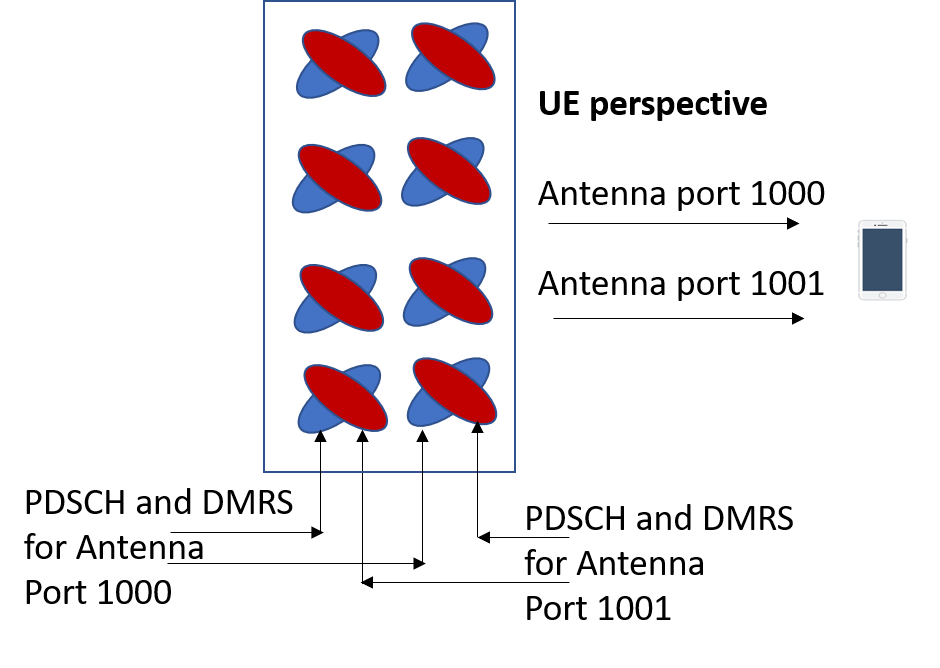
Example 1: One to One Mapping
One to One example, 2*2 MIMO case, antenna ports = 1000 & 1001. Antenna port 1000 is mapped onto one physical antenna while antenna port 1001 is mapped onto another physical antenna
From the UE perspective, there are two downlink transmissions one PDSCH and its DMRS associated with antenna port 1000, and another PDSCH and its DMRS associated with antenna port 1001. The UE does not require knowledge of which physical antenna elements were used for the two transmissions.
Example 2: One to Many Mapping
In other cases, when there is a one-to-many mapping between antenna port and physical antenna element. This may be done when using the higher operating bands which require beam-forming.
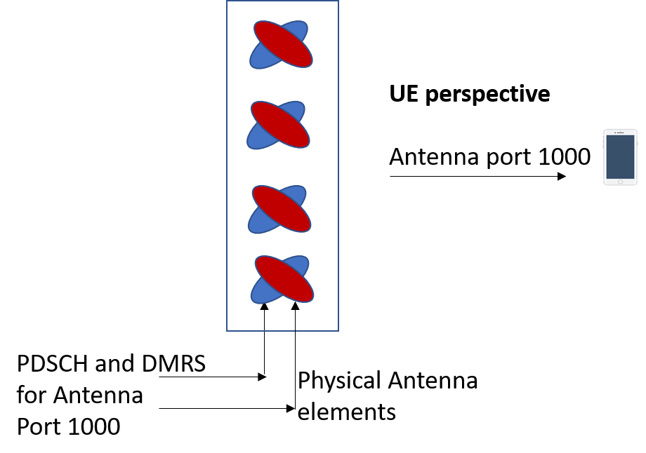
Beam-forming uses multiple physical antenna elements to direct the downlink transmissions towards a specific UE. This is typically achieved using an antenna array consisting of multiple columns of cross-polar antenna elements.
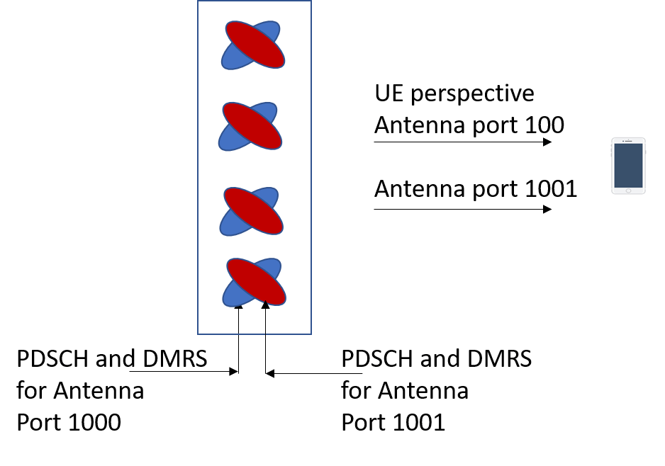
Example 3: One to Many Mapping
In this case, antenna ports 1000 and 1001 are each mapped onto multiple physical antenna elements. This provides beam-forming but with less gain and directivity than the first example because there are fewer physical antenna elements per antenna port
From the UE perspective, the first example and this example are the same, i.e. in both cases, the UE receives antenna ports 1000 and 1001.
The beam-forming helps to improve the link budget but is transparent to the UE, i.e. the UE does not require any explicit knowledge of the beam forming at the Base Station.
Related Post:
- 5G NR Antenna Ports – Logical and Physical Antenna Ports
- 5G NR Total Transmit Power | Maximum Cell Transmit Power | Reference Signal Power
- 5G NR Base Station Types
- 5G NR Base Stations Classes
- 5G NR Transmitter Signal Quality Frequency Error
- 5G NR Transmitter Signal Quality Time Alignment Error