Explain LTE Frame Structure both for FDD and TDD
Time duration for one frame (One radio frame, One system frame) is 10 ms. This means that we have 100 radio frame per second.
Let’s look at the frame structure:
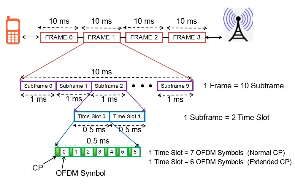
- Some of high level description you can get from this figure would be
- Number of subframe in one frame is 10
- Number of slots in one subframe is 2. This means that we have 20 slots within one frame.
- And one slot is made up of 7 small blocks called ‘symbol’.
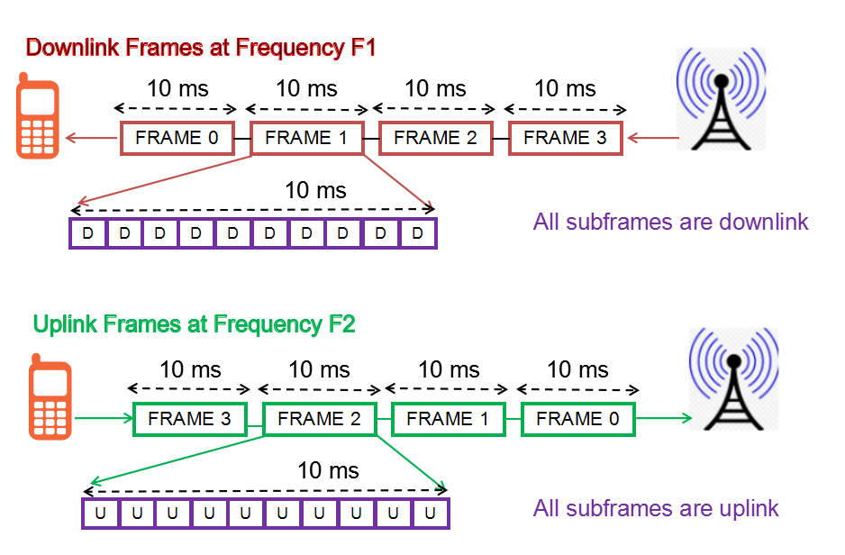
The frame structures for LTE differ between the Time Division Duplex, TDD and the Frequency Division Duplex, FDD modes as there are different requirements on segregating the transmitted data
There are two types of LTE frame structure:
- Type 1: used for the LTE FDD mode systems.
- Type 2: used for the LTE TDD systems.
Type 1: FDD Frame Structure
As LTE FDD is full duplex system, means both the downlink and uplink transmission happens at the same time at different frequencies.
Type 2: TDD Frame Structure
In TDD, the transmission is divided into time domain, means at one moment of time either downlink subframe is transmitted or uplink.
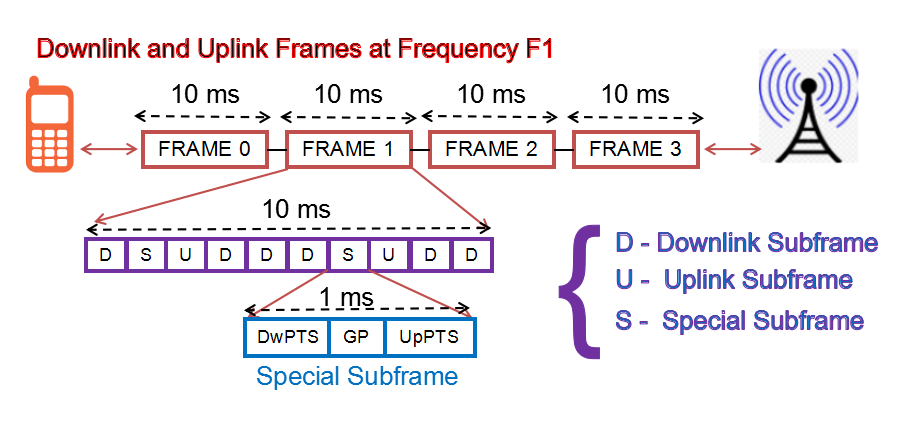
As one can see in above image, one frame is divided into 10 subframes (1ms each), and that subframe can be either downlink, uplink or special subframe.
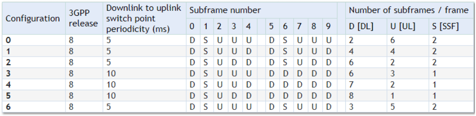
Now the question comes, who decides the sequence of these subframes. That has been defined by 3GPP with the name TDD Frame Configurations. There are fixed patterns of these configurations and network operator has to choose out of these defined patters. There are total 7 TDD configurations as shown below:
And there comes a Special subframe which comes when there is transition from downlink subframe to uplink subframe. It has three parts – DwPTS(Downlink Pilot Time Slot),GP (Guard Period) and UpPTS (Uplink Pilot Time Slot) and all of these have configurable lengths, which depends upon Special subframe configuration.
Special subframe configuration as shown below:
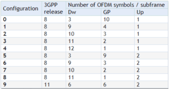
- DwPTSis considered as a “normal” DL subframe and carries reference signals and control information as well as data for those cases when sufficient duration is configured. It also carries PSS.
- GPis used to control the switching between the UL and DL transmission. Switching between transmission directions has a small hardware delay for both UE and eNodeB and needs to be compensated by GP. GP has to be large enough to cover the propagation delay of DL interferes. Its length determines the maximum supportable cell size.
- UpPTSis primarily intended for sounding reference signals (SRS) transmission from UE. Mainly used for RACH transmission.
Related Posts:
- LTE eNodeB Schedulers and Different Scheduling Types
- LTE EUTRAN Bands
- Feature Group Indicators (FGI bits) in LTE Rel. 8, Rel. 9, Rel. 10
- Dual Connectivity (DC) Definition, Protocol Architecture, DC and CA Comparison
- Multi Carrier Cell Reselection in LTE
- Maximum Coupling Loss (MCL) and Maximum Path Loss (MPL)


