Dual Connectivity, Protocol Architecture, DC and CA Comparison
Dual Connectivity
Dual connectivity (DC) is a 3GPP Release 12 feature for small cell enhancement. Similar to carrier aggregation (CA), it aims to utilize the radio resource within multiple carriers to improve UE throughput. The difference between DC and CA is in their application scenarios and their implementation.
As per 3GPP 36.300, Dual Connectivity is a mode of operation where a a multiple Rx/Tx capable UE in RRC CONNECTED mode can be configured to utilize the radio resource of two distinct schedulers, located in two eNBs namely Master eNB and Secondary eNB connected via a non-ideal back-haul over the X2 interface.
Dual Connectivity Properties:
- Dual Connectivity (DC) allows a UE to simultaneously transmit and receive data on multiple component carriers from two cell groups via master eNodeB (MN) and secondary eNodeB (SN)
- DC is for non-ideal backhaul, e.g., relatively large delay between nodes
- DC can increase user throughput, provide mobility robustness, and support load-balancing among eNodeBs
- In DC, user traffic is split between carriers in PDCP layer and data bearer is known split bearer
- DC and CA are not mutually exclusive; they can be implemented togther
- In DC, a UE has two C-RNTI: one in MCG and C-RNTI in SCG, it has an always-active cell in MCG and another always-active cell in SCG, and it has separate PUCCH resource in MCG and SCG
- The configuration between master eNB (MeNB) and secondary eNB (SeNB) is independent, e.g., bandwidth, number of component carriers, frame structure of each carrier (FDD or TDD), etc.
- In control plane, there is only one S1-MME connection and it is between MME and MeNB.
- RRC connection only terminates at MeNB; there is no RRC entity in SeNB. All SeNB-related RRC configuration is transmitted to MeNB which then transmits RRC message to UE.
Definition for Dual Connectivity.
- Master eNB (MeNB) is the eNB which terminates at least S1-MME or both S1-MME and S1-U
- Secondary eNB (SeNB) is the eNB that is providing additional radio resources.
- Master Cell Group is a group of serving cells associated with the MeNB, comprising of the PCell and optionally one or more SCells.
- Secondary Cell Group is a group of serving cells associated with the SeNB, comprising of PCell and optionally one or more SCells.
- MCG Bearer is a bearer whose radio protocols are only located in the MeNB to use MeNB resources only
- SCG Bearer is a bearer whose radio protocols are only located in the SeNB to use SeNB resources.
- Split Bearer is a bearer whose radio protocols are located in both the MeNB and the SeNB to use both MeNB and SeNB resources
Dual Connectivity Protocol and Network Architecture
In Dual Connectivity, the radio protocol architecture that a particular bearer uses depends on how the bearer is setup. Three bearer types exist: MCG bearer, SCG bearer and split bearer. Those three bearer types are depicted on figure below.
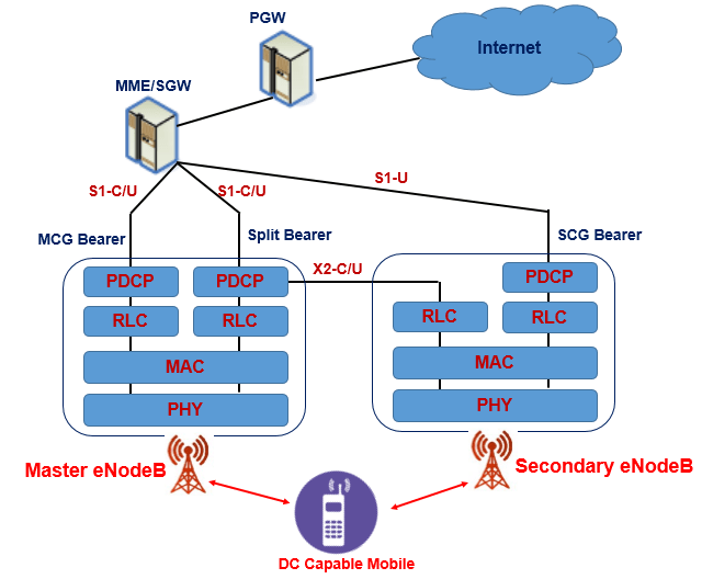
RRC is not shown in picture but it is located in MeNB and SRBs are always configured as MCG bearer type and therefore only use the radio resources of the MeNB.
Control Plane for Dual Connectivity (CP for DC)
Inter-eNB control plane signalling for DC is done by X2-C interface signalling and towards MME it is done by S1-C interface signalling. There is only one S1-C connection per DC UE between the MeNB and the MME. Each eNB should be able to handle UEs independently, i.e. provide the PCell to some UEs while providing SCell(s) for SCG to others. Each eNB involved in DC for a certain UE controls its radio resources and is primarily responsible for allocating radio resources of its cells. Respective coordination between MeNB and SeNB is performed by X2 interface signalling.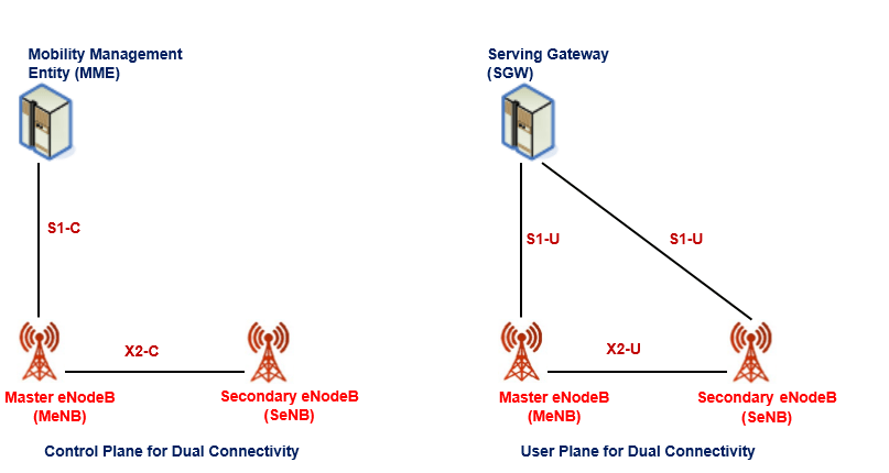
User Plane for Dual Connectivity (UP for DC)
For dual connectivity two different user plane architectures are allowed
- First, in which the S1-U only terminates in the MeNB and the user plane data is transferred from MeNB to SeNB using the X2-U
- Second, where the S1-U can terminate in the SeNB. Figure above shows different U-plane connectivity options of eNBs involved in DC for a certain UE.
Different bearer options can be configured with different user plane architectures. U-plane connectivity depends on the bearer option configured:
- For MCG bearers, the S1-U connection for the corresponding bearer(s) to the S-GW is terminated in the MeNB.
The SeNB is not involved in the transport of user plane data for this type of bearer(s) over the Uu. - For split bearers, the S1-U connection to the S-GW is terminated in the MeNB. PDCP data is transferred
between the MeNB and the SeNB via X2-U. The SeNB and MeNB are involved in transmitting data of this
bearer type over the Uu. - For SCG bearers, the SeNB is directly connected with the S-GW via S1-U. The MeNB is not involved in the
transport of user plane data for this type of bearer(s) over the Uu.
if only MCG and split bearers are configured, there is no S1-U termination in the SeNB
CA and DC Comparison
- Carrier aggregation (CA) allows a UE to simultaneous transmit and receive data on multiple component carriers from a single eNodeB where as Dual Connectivity (DC) allows a UE to simultaneously transmit and receive data on multiple component carriers from two cell groups via master eNodeB (MN) and secondary eNodeB (SN)
- CA can improves peak rates as well as user throughput at low load and DC can increase user throughput, provide mobility robustness, and support load-balancing among eNodeBs
- CA is for the scenarios where the backhaul between nodes is ideal, while DC is for non-ideal backhaul, e.g., relatively large delay between nodes.
- In CA implementation, user traffic is split between carriers in MAC layer, while in DC implementation, it is split in PDCP layer. In DC, the data bearer which is split in PDCP is called split bearer.
- CA and DC are not mutually exclusive; instead, they can be jointly implemented for the same UE e.g, there are multiple carriers in the master cell group (MCG) and multiple carriers in the secondary cell group (SCG)
- A DC UE has two identities: one C-RNTI in MCG and another C-RNTI in SCG, it has an always-active cell in MCG and another always-active cell in SCG, and it has separate PUCCH resource in MCG and SCG. In CA, there is only one common C-RNTI across all component carriers, and there is only one PUCCH which is on PCell.
References:
- 3GPP 36.300 Evolved Universal Terrestrial Radio Access Network (E-UTRAN);Overall description
- https://www.linkedin.com/pulse/lte-dual-connectivity-zhou-hongwei/
Related Posts:
- MASTER INFORMATION BLOCK (MIB)
- PLMN Selection in LTE
- LTE Cell Camping and Selection Procedure
- LTE Channels: Logical, Transport and Physical Channels Details and Mapping
- Hybrid Automatic Repeat Request (HARQ) in LTE FDD
- LTE eNodeB Schedulers and Different Scheduling Types