Why characteristics impedance of RF transmission lines is kept 50 Ohms ?
If you play with RF PCB where RF devices such as amplifiers, filters, couplers etc. are mounted, or you come across RF coaxial cables, you probably know the fact that transmission line impedance of rf traces is kept at 50 Ohm. And this is also known as characteristics impedance of transmission line.
Why this impedance is a special numbers? It’s not an accident of course, and there is a reason for each one. Today, we’re going to take a quick look at 50 ohm transmission line.
There are two factors that drive 50 Ohm impedance: losses and power.
loss and power versus impedance
If we can plot transmission line loss versus characteristic impedance. It turns out that insertion loss is minimum at around 77 ohms. And on the other hand, if we plot maximum power transfer versus characteristic impedance, we get maximum power at around 30 Ohms.
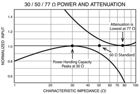
Trade-off between losses and power
It all comes down to the characteristic impedance value for maximum power transfer being 30 ohms, while the characteristic impedance for theoretical minimum attenuation (loss) is 77.5 ohms. 50 ohms is more or less in the middle, between these two values, so 50 ohms was settled upon as a standard characteristic impedance. It really is as simple as that.
So in the field of RF and Microwave where there is a trade-off between the losses and power, transmission line is choosen at 50 Ohm impedance value.
On the other hand, when minimal loss is required in long coaxial cable runs, such as in cable or satellite TV, the concern is less with optimizing power transfer, so the higher-impedance 75 ohm cable and connectors are used in those systems.