5G SR – Scheduling Request
Scheduling Request
SR also known as Scheduling Request is a very famous word for telecom Dev, Test, and Optimization Engineers. It is a Layer 1 (Physical Layer) signal or message sent by the UE to gNB to ask for an Uplink (UL) grant to send the Uplink data over PUSCH. The UL grant is sent to UE by gNB over PDCCH transmission in DCI Format 0_0 or Format 0_1.
In other words, we can say that UE initiates the SR to gNB saying “hey! I have some data to send, please give me some grant”.

Key Pointers
- SR aka Scheduling Request is a Physical Layer message to UL grant to send Uplink data on PUSCH
- SR is sent on the PUCCH uplink channel
- UL grant is provided to UE in PDCCH transmission DCI Format 0_0 or Format 0_1
- SR mechnism is control by MAC Layer
- SR is not Service Request which is a NAS Layer message
- gNB can configure a UE with Max SR to get UL grant
- SR can be used to declare Radio Link Failur if SR-COUNTER reached to sr-TranMax
- UE is not allowed to send SR when it is in Meas Gap and sr_ProbhitTimer is running
Scheduling Request Control Flow
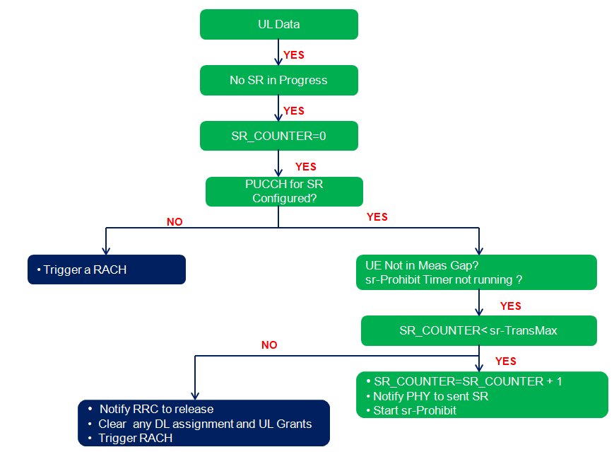
We know SR is a physical layer procedure but it is control by MAC layer. Following figure illustrate the over all SR control flow as per 3GPP specification 38.321 section 5.4.4.
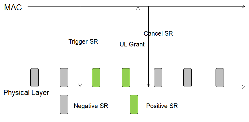
- Positive SR and Negative SR: The UE does not always need to send SR requests, so specification has defined Postive and Negative SR.
- For Positive SR, UE has SR requests to send, and the physical layer needs to send SR/PUCCH.
- At the time point, of the SR resource, UE does not send SR requests, called as a Negative SR.
- SR Transmission not allowed: SR will NOT be transmitted under the following conditions:
- SR opportunity falls in measurement gap interval or
- another SR-Prohibit timer is running or
- DL PDCCH with UL resources is received.
- sr-TransMax – SR Max Transmissions Condition: When the maximum number of SR requests are sent and the UL grant cannot be obtained, the random access process is triggered by sending the PRACH to obtain the uplink scheduling. It does following when sr-TransMax stiuation occurs.
- UE releases PUCCH resources and SRS configuration
- Clear Configured DL assignments and Configured UL Grants
- Clear PUSCH Resource for sending semi-persistent CSI
- UE starts RACH Procedure (i.e RACH with UL DATA_ARRIVAL)
- gNB reconfigures PUCCH resources and SR configuration
SR Configuration Parameters
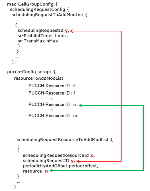
SR Configuration is not straigth forward and having multiple interdependancies with mac-CellGroupConfig and PUCCH-config as shown in below figure.
SR RRC Parameters
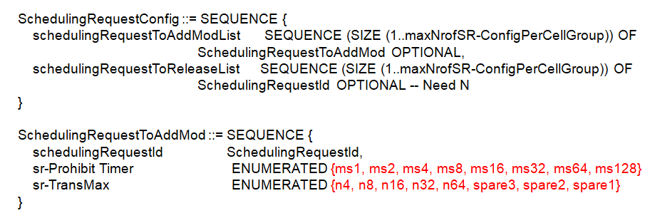
Following figures shows the list of RRC parameters as per 3GPP 38.331 for SR.
- schedulingRequestId : Different SR configurations are distinguished by schedulingRequestId. It sused to modify a SR configuration and to indicate, in Logical Channel Config, the SR configuration to which a logical channel is mapped and to indicate, in SchedulingRequestresourceConfig, the SR configuration for which a scheduling request resource is used. The specific SR corresponds to the physical layer resource configuration. In PUCCH-Config, the configuration is configured separately for each uplink BWP, and the schedulingRequestResourceId is used to distinguish different resource configurations, in which the schedulingRequestID is associated. Of course, it also includes the SR sending time point configuration and the corresponding PUCCH Resource configuration.
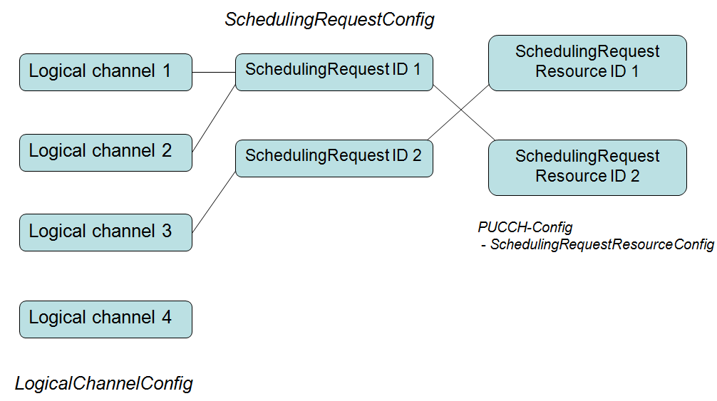
One logical channel corresponds to at most one SchedulingRequestID, and multiple logical channels can share one SchedulingRequestID. For Logical Channel 4 in above figure, since SR is not configured, if there is data transmission on the logical channel , the uplink scheduling can only be obtained through the RACH procedure.
- sr-ProhibitTimer : Timer for SR transmission in ms on PUCCH
- sr-TransMax : Maximum number of SR transmissions
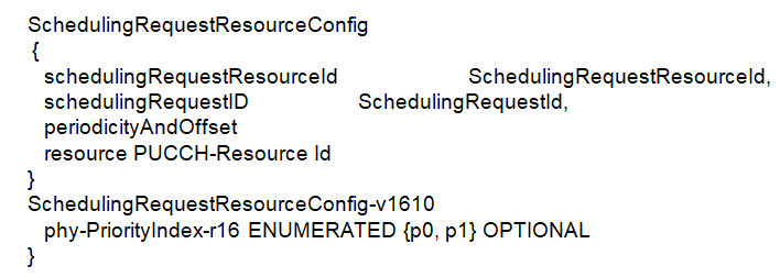
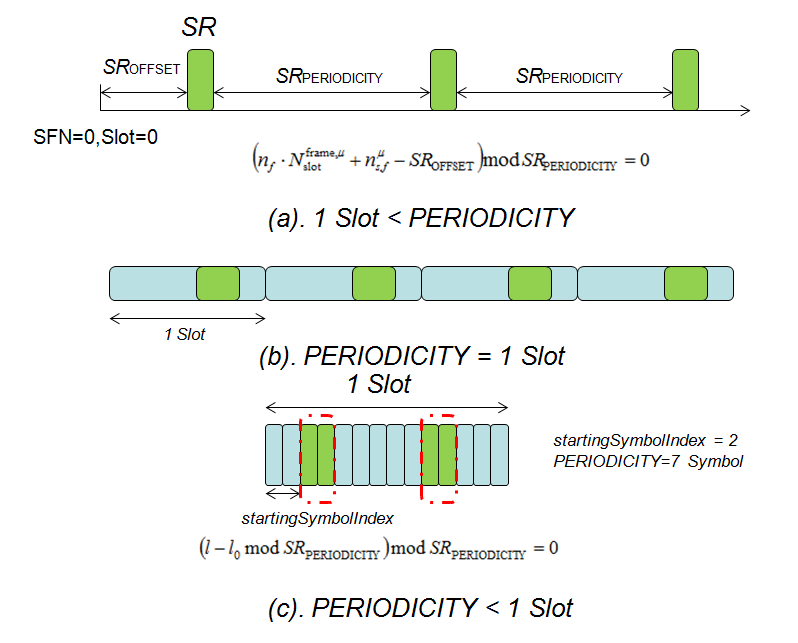
- periodicityAndOffset : periodicityAndOffset in SchedulingRequestResourceConfig determines the sending time position of the SR and defined in number of symbols or slots. Note that the minimum period is 2 Symbols. As per 3GPP 38.213 following periodicities may be configured depending on the chosen subcarrier spacing.
- SCS = 15 kHz: 2sym, 7sym, 1sl, 2sl, 4sl, 5sl, 8sl, 10sl, 16sl, 20sl, 40sl, 80sl
- SCS = 30 kHz: 2sym, 7sym, 1sl, 2sl, 4sl, 8sl, 10sl, 16sl, 20sl, 40sl, 80sl, 160sl
- SCS = 60 kHz: 2sym, 7sym/6sym, 1sl, 2sl, 4sl, 8sl, 16sl, 20sl, 40sl, 80sl, 160sl, 320sl
- SCS = 120 kHz: 2sym, 7sym, 1sl, 2sl, 4sl, 8sl, 16sl, 40sl, 80sl, 160sl, 320sl, 640sl
- phy-PriorityIndex : Indicates whether this scheduling request resource is high or low priority in PHY prioritization / multiplexing handling. Value p0 indicates low priority and value p1 indicates high priority. The UE can be provided, by phy-PriorityIndex in SchedulingRequestResourceConfig, a priority index 0 or a priority index 1 for the SR. If the UE is not provided a priority index for SR, the priority index is 0.
- resource : ID of the PUCCH resource in which the UE shall send the scheduling request. The actual PUCCH-Resource is configured in PUCCH-Config of the same UL BWP and serving cell as this SchedulingRequestResourceConfig. The network configures a PUCCH-Resource of PUCCH-format0 or PUCCH-format1
- schedulingRequestID : The ID of the SchedulingRequestConfig that uses this scheduling request resource. In the MAC configuration, each logical channel can be associated with an SR configuration.
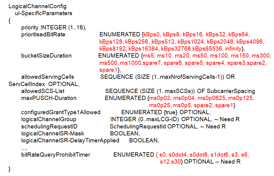
- logicalChannelSR-Mask : Controls SR triggering when a configured uplink grant of type1 or type2 is configured. true indicates that SR masking is configured for this logical channel
- logicalChannelSR-DelayTimerApplied : Indicates whether to apply the delay timer for SR transmission for this logical channel. Set to false if logicalChannelSR-DelayTimer is not included in BSR-Config.
How to know SR Periodicity in 5G NR
The parameter periodicityAndOffset can be to know the SR Periodicity. The SR Periodicity is defined in term of no. of Slots e.g 40sl, 80sl etc. and the duration of a slot changes with the subcarrier spacing (SCS). With SCS=15KHz, 1 slot = 1ms and for SCS=120KHz, 1 slot= 0.125ms.
When system is configured with SCS=15KHz and RRC indicated periodicityAndOffset value as 80sl it mean SR Periodicity is 80ms, but with SCS=120KHz and periodicityAndOffset 80sl is not 80ms, it will be 80*0.125= 20ms.
Related Topics:
- 5G NR Antenna Port – Logical and Physical Antenna Mapping
- 5G NR Physical Layer Timing Unit
- 5G Subcarrier Spacing, Frame and Subframe, Slot and OFDM Symbol
- Motivation Behind Having Multiple Numerology in 5G NR
- 5G NR Resource Block Definition and RB calculations
- 5G NR Modulation and Coding Scheme (MCS)
References
- 3GPP TS 38.321: MAC specification (Release 15)
- 3GPP TS 38.211: Physical channels and modulation
- 3GPP TS 38.300: NR and NG-RAN Overall Description