5G NR Physical Cell ID (PCI) Planning
5G NR PCI Planning
Each 5G NR cell corresponds to a Physical Cell ID (PCI) and it is used to distinguish cells on the radio side. The PCI planning for 5G NR is very much similar to PCI planning for LTE and scrambling code planning for 3G UMTS. Bad or wrong planning can affect the synchronization procedure , demodulation, and handover signaling and degrade the network performs. PCI Planning should be simpler for NR compare to LTE because there are double as many PCIs available for allocation.
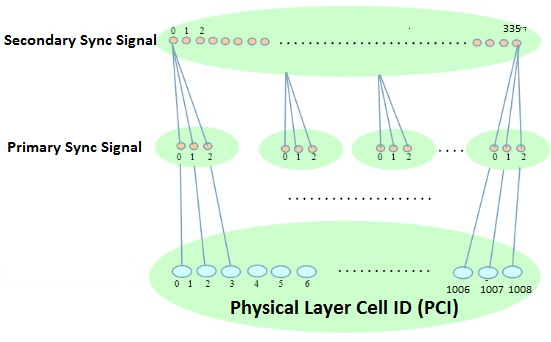
In 5G New Radio, there are 1008 unique PCIs compare to LTE 504 PCIs and it is given by following formulation
![]()
where
- N (1) ID = Secondary Synchronization Signal (SSS) and its range is from {0, 1….335}
- N (2) ID = Primary Synchronization Signal (PSS) and its range is from {0, 1, 2}
5G Network PCI Planning Principles
5G PCI planning should be done keeping following thing in mind
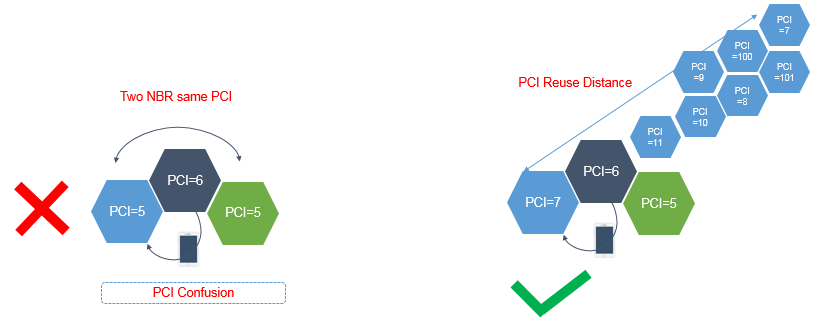
- Avoiding PCI Collision: As part this principle of network planning, neighboring cells cannot be allocated the same PCI. If neighboring cells are allocated the same PCI, only one of the neighboring cells can be synchronized during the initial cell searching in the overlapping area. However, the cell may not be the most appropriate one. This phenomenon is called collision. So the physical separation between cell using the same PCI should be sufficient to ensure the UE never received the same PCI from more than one cell. This can be achieved by maximizing the re-use distance for PCI.
- PCI collision can result delay in DL synchronization in overlapping zone
- High BLER and decoding failure of physical channels scrambled using PCI
- Handover failures
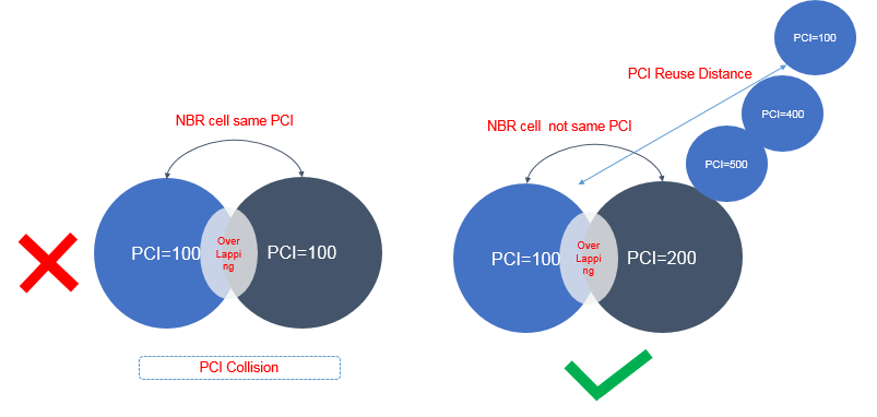
- Avoiding PCI Confusion: Under this principle of network planning, two neighboring cells of one cell cannot be allocated with the same PCI. If they are allocated the same PCI, the base station will not know which is the target cell upon a handover request of a UE. This shall create a confusion situation. The approach while allocating PCI should be such that a cell should not have multiple neighbors using the same PCI and the physical separation between the cells using the same PCI should be sufficient large enough to avoid neighbor confusions.
- Minimizing Impact on network performance : Based on the design of different Physical layer signals (PSS, DMRS & SRS), channels (PUSCH, PUCCH) and time-frequency allocation, PCI planning must consider following Mod to reduce interference. As per this Mod Principle UE should not be able to simultaneously receive multiple PCI with following modes:
-
-
- PCI Mod 3
- PCI Mod 4
- PCI Mod 30
- Example of “Mod 3 PCI” the neighboring cell should be allocated PCI 25 and 28 because both has Mod 3 as value 1
-
- Why Mode 3 : PCI Mod 3 rule is based on relationship between PCI and sequence generated by PSS. There are 3 PSS (0,1,2) which are reused across the network . The cells having same ‘PCI Mode 3’ result will use the same PSS and simulation results has shown that if UE receive same PSS from multiple cell result in delay in cell acquisition and misleading channel estimation. Over all it will impact on synchronization delay and user experience.
- Why Mode 4: PCI Mod 4 rule is based on subs-carrier positions of DMRS for PBCH. The subcarriers are allocated to DMRS using ‘Mod 4’ computation. If neighboring cell use PCI having same Mod 4 value, shall result in DMRS to DMRS interference.
- Why Mode 30: DMRS for PUCCH/PUSCH and SRS based on the ZC sequence, 30 groups of roots. The roots are associated with the PCI, hence the neighbor cell should not have PCIs having same Mod 30 value to ensure the uplink inter cell interference.
-
Related Posts
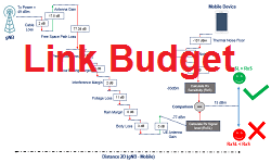
- 5G Network RF Planning – Link Budget Basics
- 5G mm Wave 28GHz Band Link Budget-n257
- 5G NR Physical Cell ID (PCI) Planning
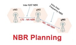
- 5G NR Network Relationship – Neighbor Planning