Multiplex Access Technique in 5G
Multi-path propagation in a radio signal transmission causes time delays, signal distortions, and so on. Let us discuss basic theories of multiple access techniques utilized in 1G-to-5G systems for solving such problems.
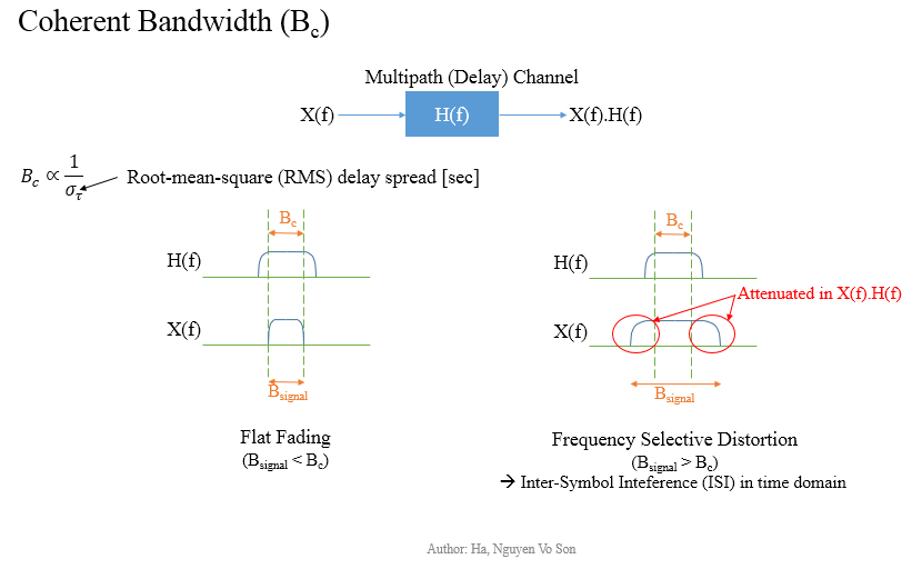
Coherent Bandwidth and Fading Channel
A base station (UMTS-NB/eNB/gNB) transmits a signal to a User Equipment (UE) in multiple directions, so received signals can be delayed or attenuated. In frequency domain, if the signal bandwidth is less the coherent bandwidth, then the signal is preserved without any distortion. But there will be attenuation, if signal bandwidth is larger than the coherent bandwidth, which is referred to as a Frequency Selective Fading Channel.
Frequency Division Multiplex Access (FDMA)
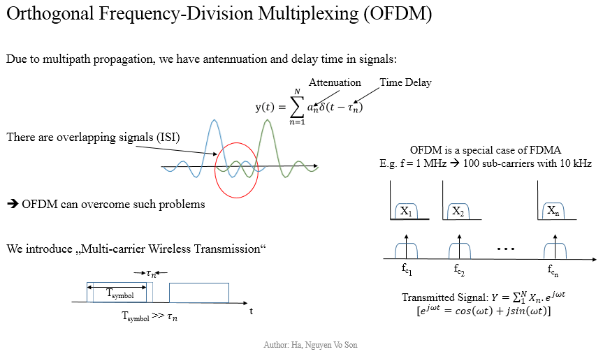
FDMA has been used for 1st generation systems (1G). Fundamentally we split up a bandwidth to small chunks for transmitting our symbol at a higher symbol duration, for example 20 MHz (maximum channel bandwidth in LTE) can be divided into 1200 sub-carriers and each sub-carrier has a bandwidth of 15 kHz, which is known as Multi-carrier Transmission technique. In total it will be 18 MHz and the other 2 MHz is used for guard bands (further information can be found in 3GPP 36.104). In the previous example, we transmits a symbol in 66.7 ms instead of 0.05 us, i.e. 1/(15 kHz) rather 1/(20 MHz). It significantly reduces the proportion of a time delay in the transmission, e.g. 1-us delay in comparison with a symbol duration of 0.05 us and 66.7 ms respectively, and it thus avoids overlapping symbols/signals in time domain. The idea is illustrated in the following image’s left-bottom corner.
In the previous section, we mention that signal distortion happens under a Frequency Selective Fading Channel. In practice, we would deploy a channel equalization/equalizer within our broadband processing system to reduce the distortion. I will explain further about channel equalization techniques in another article about Multiple-Input Multiple-Output (MIMO) systems together with beam-steering and energy efficiency. In the following part, I am introducing OFDMA as a technique to solve all above mentioned problems caused by multi-path propagation, delay spreads, frequency selective fading channels and inter-channel interference (ICI).
Orthogonal Frequency Division Multiplex Access (OFDMA)
OFDMA is a special case of FDMA. All of subcarriers’ frequencies are orthogonal to one another, which means overlapping signals among subcarriers are eliminated. However, there are still Inter-Symbol Interference (ISI) caused by multipath propagation, so Cyclic Prefix (CP) is inserted to eliminate ISI. Since OFDM uses composite Inverse Fast Fourier Transform (IFFT) samples, we copy the end part of the symbol period and place them at the beginning. For example a 15 kHz subcarrier has 14 symbols/slot, there is a 5.2 ms CP at the beginning and all other CPs are 4.7 us. Each radio frame lasts for 10 ms and has 10 sub-frames (1 ms/sub-frame), and a number of slots per a frame depends on the carrier frequency.
What happens if we use CPs with 0 values instead of copying the ending parts ?
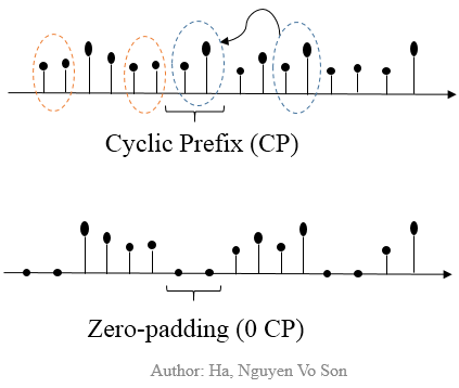
Technically it is denoted as zero-padded OFDM symbols. We need to discuss firstly about Circular Convolution (cc), which converts Frequency Selective Multipath Channel into Flat Fading Channel. Then, we will see that zero-padded symbols eliminating ISI, but causing an inefficient decode at receivers.
Example: Let us consider a signal part:
- x(0), x(1), …, x(N-1)
We copy L symbols at the end as a Cyclic Prefix (the blue part in the above Figure), so we have:
- x(N-L), …, x(N-1), x(0), x(1), …, x(N-1)
Note: bold text is in purpose of highlighting a possible cyclic prefix added before our first symbol x(0) with n=0. Let us imagine a channel h(n) as a transmission channel, so we have outputs at our (causal-system) receivers as the following y(n):
- y(0) = h(0).x(0) + h(1).x(N-1) + h(2).x(N-2) + … + h(L-1).x(N-L+1),
- y(1) = h(0).x(1) + h(1).x(0) + h(2).x(N-1) + … + h(L-1).x(N-L+2),
and so on. Notice that:
- y(0) = h(0).x(0) + h(1).x(N-1) + …,
- y(1) = h(1).x(0) + h(0).x(1) + …
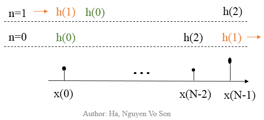
We realize that there is a circular shift between h(n) and x(n) as the following diagram based on a helpful study source:
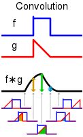
What is Convolution
A convolution in the time domain is equivalent to a standard multiplication in the frequency domain via Fourier Transform (FT). Therefore, we achieve a Flat-fading system Y(w) = H(w).X(w) from y(n) = h(n) cc x(n) (cc denotes circular convolution). It means that we will not achieve a similar system if we use zero-padded symbols. Copying an end part of IFFT-OFDM symbols as Cyclic Prefixes is thus a better approach than using 0 values for Cyclic Prefixes.
Just a recap of convolution, I take directly a figure on Wikipedia:
How can OFDM symbols be transmitted over the air?
Data signal is modulated with sub-carrier signals by a specific modulation scheme, e.g. Quadrature Phase Shift Keying (QPSK). Then, we sample its output by IFFT and insert Cyclic Prefix. OFDM symbols are then converted to analog by Digital Analog Converter (DAC), and modulated with a radio frequency to transmit over the air (modulated = basically shifted to radio frequency on the frequency domain).
Summary
- There is signal distortion under Frequency Selective Fading Channel when our signal bandwidth is larger than the coherent bandwidth.
- Frequency Division Multiplex Access (FDMA) divides a channel bandwidth into multiple sub-carrier bandwidths, and thus avoiding overlapping signals due to transmission delay in multi-path propagation.
- Orthogonal Frequency Division Multiplex Access (OFDMA) eliminates Inter-Symbol Interference (ISI) by orthogonal signals (in consideration of frequencies) and supports efficient decoding algorithm at receivers by (non-zero) Cyclic Prefixes.
Article is submitted by Ha, Nguyen Vo Son (MS from Technical University of Munich)

- 5G NR Bandwidth Part(BWP)
- 5G NR BWP Types and BWP Operations
- 5G NR Control Plane Latency
- 5G NR User Plane Latency
- 5G Reference Network Architecture
- 5G Network Sharing: Concept, Benefits and Architectures
- Hybrid Core Network – 4G Core to 5 G Core Interconnection
- Deployments Scenarios for 5G-NR
- 5G Key Performance Indicator Definitions Template by 3GPP


