IEEE 1588: Precision Time Protocol (PTP) for Telecom Networks
Overview of IEEE 1588 PTP
PTP is a network based time synchronization protocol, but instead of millisecond-level synchronization, PTP networks aim to achieve nanosecond or even picosecond-level synchronization. Synchronization is very critical for telecom networks nodes and nodes can have states like free run, Frequency Locked , Phase Locked, Holdover etc. as shown in following figure.

PTP Protocol Characteristics
- The PTP standard was originally defined in 2002.
- The second and current version of the standard was published in 2008 and it is known as “IEEE 1588-2008” IEEE Standard for a Precision Clock Synchronization Protocol for Networked Measurement and Control Systems
- PTP time stamping is so accurate because it uses hardware time stamping instead of software, and PTP equipment is dedicated to one specialized purpose: keeping devices synchronized.
- PTP networks have much sharper time resolutions, and unlike NTP
- PTP devices will actually time stamp the amount of time that synchronization messages spend in each device, which accounts for device latency.
- It works on Master and slave concept, slave node tries to follow timings from Master node
- It has two flavors 1 step and 2 step
Types of Synchronization
IEEE 1588 PTP can be used to achieve the following types of synchronization in telecom networks:
- Frequency Sync: The nodes in the network have the 48 bits and in particular the 32 bits of time change at the same rate, without caring necessarily what the 48/32 bit values are. Telecom applications initially used IEEE 1588 to distribute frequency only.
- Phase Sync: The nodes in the network not only have the 48/32 bits of time changing at the same rate, but have at least the seconds boundary time occurring at the same time. That is to say, when the nanoseconds time rolls over and increments the seconds time, all nodes do this at the same time. These nodes may not necessarily need to know what the year, month, day and hour are.
- Time of Day Sync: The nodes in the network are not only frequency and phase synchronized, but they also want to know what the year, month, day, hour, and seconds are, along with nanoseconds.
IEEE 1588 PTP Roles
IEEE 1588 PTP is designed for primarily following two main roles to distribute time:
- Master – Master node role distributes time to Slaves. A Master node can also be a Grand Master (GM), that gets its time from a primary reference source, typically a GPS satellite signal.
- Slave – Slave devices are remote from the Master and is synchronizing to it.
How IEEE 1588 PTP Works
- The IEEE 1588 Master node transmit periodically a SYNC message to the Slave device. As the SYNC message leaves the Master’s physical interface, it captures a running time stamp in the Master, shown as T1. In the 1-Step mode that is being illustrated here, the Master sets the “Origin Time Stamp” field in the SYNC message to T1 before the message completely exits the interface.
- The Slave node receives the SYNC message and its running time stamp clock captures the time (T2) that the SYNC message starts to arrive at its physical port.
- Although the Slave could set its time stamp clock to that of the Master using T2, it would leave the Slave’s clock in an inaccurate state due to the propagation delay of the wired network. Also, the Slave’s time stamp clock will be running slightly faster or
slower than the Master’s in the beginning stages. Next Slave node to tries to frequency lock its clock with the Master’s. During this phase, the Slave will only receive SYNC messages until it believes its time stamp clock is changing at the same rate as the Master’s. - After frequency locking, the Slave will next proceed to determine what the delay is between itself and the Master node.
- Although the Slave could set its time stamp clock to that of the Master using T2, it would leave the Slave’s clock in an inaccurate state due to the propagation delay of the wired network. Also, the Slave’s time stamp clock will be running slightly faster or
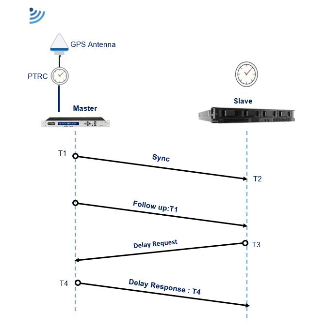
- The Slave calculates what the delay is by sending a DELAY REQUEST message to the Master. As the message starts to be transmitted out the Slave’s physical interface, the Slave’s running time stamp clock is used to capture the time (T3) and the Slave stores this time while it waits for the reply.
- The Master receives the DELAY REQUEST and uses the Master’s running time stamp clock to capture the time (T4) as the message starts to be received on its physical interface. After retrieving the captured T4 value, the Master will shortly thereafter send
the Slave a DELAY RESPONSE containing the captured T4 value. - The Slave receives the DELAY RESPONSE message and extracts the T4 value in it.
- The Slave can calculate the reverse delay as (T4-T3). It can then adjust its time stamp clock to account for the wire delay, at least in the beginning stages. After a few iterations of this to make sure the reverse delay measurement is stable, the
Slave can now measure the forward delay using captures of (T2-T1). - Finally, instead of using just the reverse delay, IEEE 1588 uses both the forward and reverse path delay in steady state to account for the wire delay. This delay is called the mean path delay, calculated as {(T4-T3) + (T2-T1)}/2. Once this is computed, the Slave will readjust its clock to align with the Master’s which now takes into account the wire delay
- The Slave can calculate the reverse delay as (T4-T3). It can then adjust its time stamp clock to account for the wire delay, at least in the beginning stages. After a few iterations of this to make sure the reverse delay measurement is stable, the
PTP Device Types
In IEEE 1588 system can be found several types of clocks:
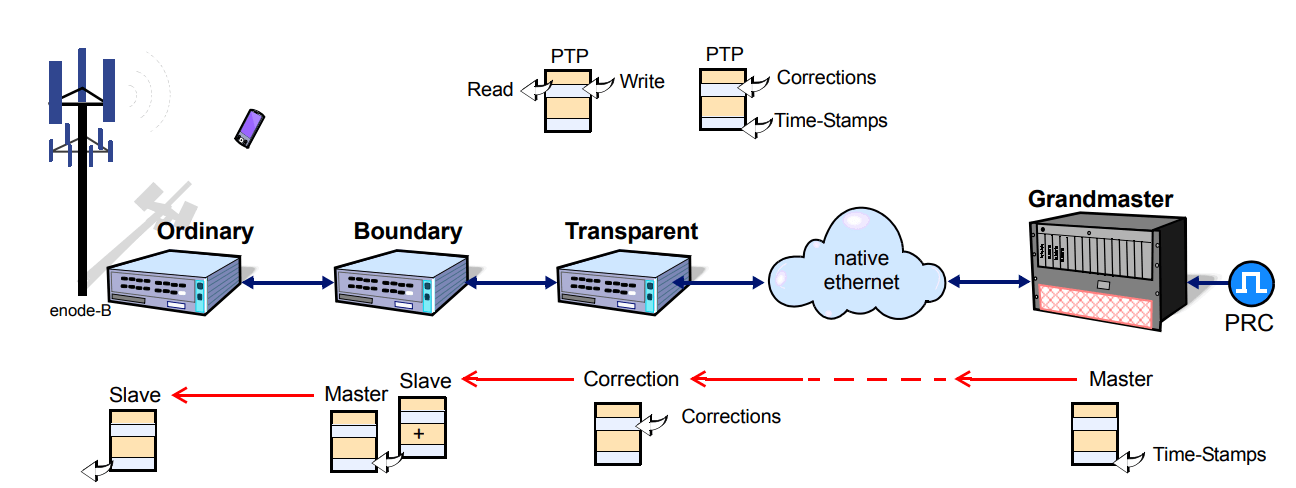
- Master Clock (MC): A master clock provides accurate time stamping to slaves clocks collocated at the downstream side.
- Grand Master (GM): A grandmaster is a the master clock situated at root timing, therefore is the clock reference, transmitting time information to the clocks of its segment. Write time stamps and responds time request from other clocks
- Transparent Clocks (TC): A transparent clocks pass through PTP messages adding in the correction field the time spent packets when traversing the device. Write corrections
- Boundary Clock (BC): A boundary clock has multiple network connections, works as slave upstream and as master downstream. Then it bridges synchronization from one segment to another. Read/Write time stamps
- Ordinary Clock (OC): It is a clock device with a single port connection that can play de role of master or slave depending on its position in the network. Read/Write time stamps.
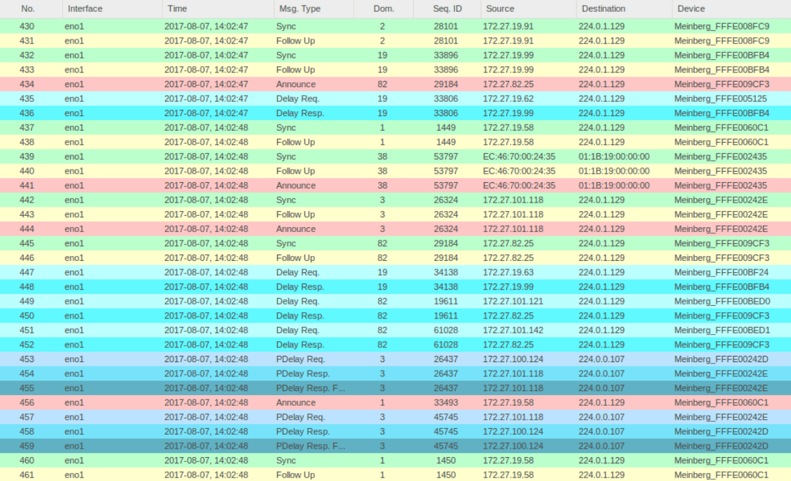
PTP Message types
PTP message are two types namely Event messages and General messages. Event messages are time-critical and General messages are not.
- Event Messages
- 00xH Sync: It used by the Master to convey time.
- 01xH Delay Request: – The Slave sends this message to the Master and used to measure delay.
- 02xH Pdelay Request: It is used between IEEE 1588 devices to measure the delay of an incoming link. Only used when Peer-to-Peer delay mechanism is used.
- 03xH Pdelay Response: It is used between IEEE 1588 devices to measure the delay of an incoming link. Only used when Peer-to-Peer delay mechanism is used.
- General Messages
- 08xH Follow Up: It is used by the Master to convey a captured time stamp of a transmitted SYNC message. This is used in 2-Step mode to send the earlier captured time stamp of a SYNC message.
- 09xH Delay Response: It is used between the Master and Slave when using End-to-End delay Mechanism to measure delay. The Master uses this to respond to the Slave.
- 0axH Pdelay Response Follow Up: It is used between IEEE 1588 devices to measure the delay of an incoming link. Only used when Peer-to-Peer delay mechanism is used with 2-Step mode.
- 0bxH Announce: It is sent and received by local clock ports with a variety of information. It can be used to determine which one out of several possible Masters is to be selected as the Best Master. It can also be used between Master and Slave to negotiate a unicast service
- 0cxH Signaling: It is used by clocks for conveying things such as how often to send messages, supporting unicast services instead of multicasting etc.
- 0dxH Management: It is used between management devices and clocks
PTP Clock Class Specifications
Lower the class means better Master Clock, its value can be from 0 to 255 decimal
- Clock Class 6: Locked with Primary Reference Clock
- Clock Class 7: PRC unlocked but still in spec
- Clock Class 13: Locked to app specific timescale
- Clock Class 14: Unlocked from app specific time, but in spec
- Clock Class 52, 187: Primary Reference Clock, unlocked and out of spec
- Clock Class 52, 193: Application specific unlocked and out of spec
- Clock Class 248: Default, if nothing else applies
- Clock Class 255: Slave Only Clock
PTP Profiles
The IEEE 1588 standard provides for custom specification of configuration options in the form of profiles. This allows other standards organizations to use IEEE 1588 as a general foundation for more specific clock synchronization standards. In each of the profile sections below, several configuration options are listed.
- Default profiles
The IEEE 1588 standard includes two default profiles, one for each of the delay measurement mechanisms.- Delay Request-Response profile (corresponds to end-to-end delay measurement)
domain 0, Announce interval 1 (range 0–4), Sync interval 0 (-1 to 1), Delay_Req interval 0 (0–5),
Announce timeout 3 (2–10), Priority1 128, Priority2 128.
path delay measurement mechanism: Default is delay request-response (e2e). Peer delay is also
allowed. Limited to a single mechanism per communication path. - Peer-to-Peer profile (corresponds to peer-to-peer delay measurement)
Same as above except that the path delay measurement mechanism default is peer delay (with delay
request-response allowed). Additionally, Pdelay_Req interval 0 (0-5).
- Delay Request-Response profile (corresponds to end-to-end delay measurement)
- Power profile (IEEE PC37.238)
For use within and between potentially widely separated power substations.- transport: layer-2, multicast
- domain 0, Announce interval 0, Sync interval 0, Pdelay_Req interval 0, Announce timeout 3 (2 for preferred grandmasters), Priority1 128, Priority2 128 (255 for slave-only clocks).
- path delay measurement mechanism: only peer delay (p2p)
- one-step recommended
- Telecommunication profile (ITU G.8265.1)
- transport: layer-3, unicast
- domain: 4, Announce timeout 2
- path delay measurement mechanism: delay request-response (e2e)
- gPTP default (IEEE 802.1AS)
This is not actually a 1588 profile, but 802.1AS, being based on IEEE 1588, is comparable to a 1588 profile.- transport: layer-2, multicast (unicast in WLANs)
- Pdelay_Req interval 0
- path delay measurement mechanism: only peer delay (p2p)
- two-step
Related Post
- O-RAN Fronthaul Synchronization Configuration
- Virtual Network Function (VNF) Definition, Architecture and Design
- Virtual Network’s Most Common Definitions
- Open RAN Network Architecture Components
- What is eCPRI, how it contributes to 5G and Open RAN?
- O-RAN Fronthaul Spilt Option 7-2x
