5G SA Inter gNB Handover – Xn Handover
Introduction
Mobility (Handover) in an important feature in any telecom generation and so it is in 5G. The basic handover procedure remains same as it was in legacy networks, i.e. UE reports measurement report with neighbor cell PCI and signal strength to source cell, source cell take the decision to start handover procedure to best target cell and Target Cell completes the Handover procedure.
In LTE, we use to have different types of Intra System (LTE to LTE) handover like X2 Based Handover, S1 Based Handover, Inter Frequency, Intra Frequency and Inter sector handovers, similarly 3GPP specification has defined different Intra system (5G NR to 5G NR) handovers, e.g. Xn based Handover, N2 or NGAP Based Handover, Intra and Inter Frequency Handovers.
In this post we will discuss about Inter gNB Xn Handover, When the UE moves from one gNB to another gNB without relolcating the UPF.
Key Pointers for Xn Handover
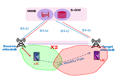
- Xn Handover is similar X2 Handover in 4G LTE
- Xn handover prerequisite is that an Xn interface must be up between source and Target gNB
- This type of Handover is only applicable for intra-AMF mobility, i.e. Xn handover cannot be used if Source and Target gNB is connected to different AMF
- Xn Handover can be Intra Frequency HO and Inter Frequency HO
- Source and Target gNB can be connected two different UPFs
- Re-Registration is required after Successful Handover if the Source gNB and Target gNB belong to different Tracking Area (TAC)
- Xn Handover is Faster Compare to N2/NGAP Handover due to short signalling path and 5G Core involved in only for switch the PDU session path
Xn-Handover Procedure

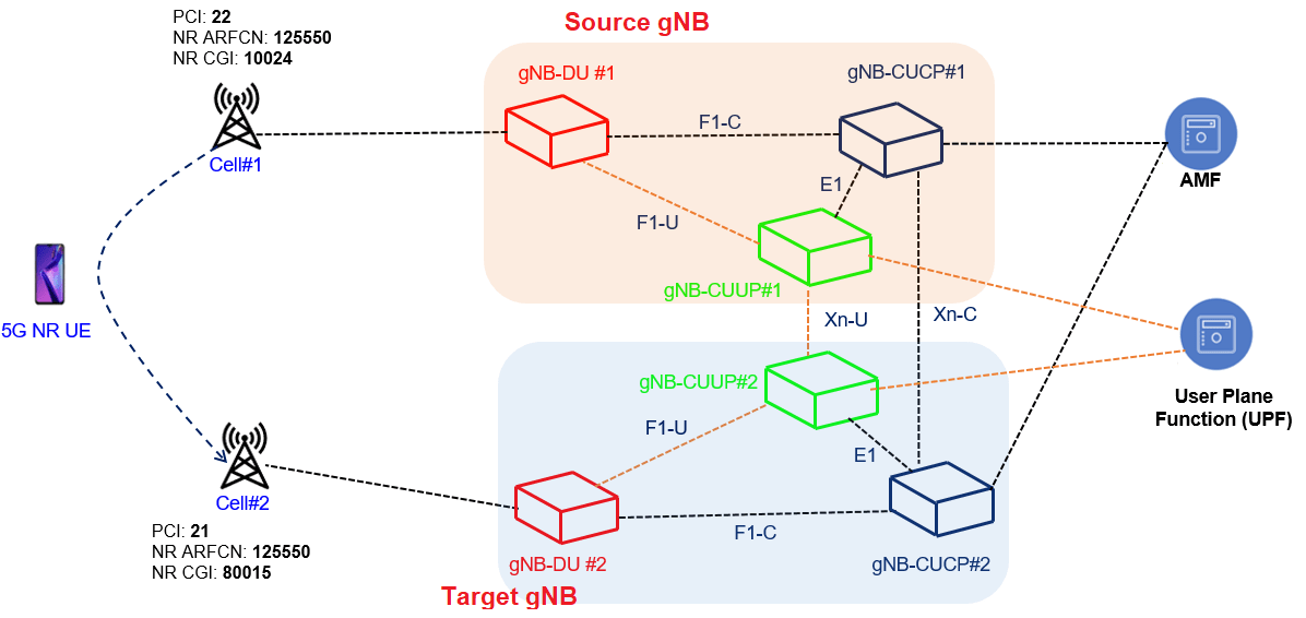
Above picture depicts the mobility scenarios where UEs is connected to source cell with PCI: 22 with gNB#1 and it is moving toward target cell#2 with PCI:21 with gNB#2. In this handover procedure the signaling will involve messaging over Xn interface using XnAP protocol and over N2 interface using NGAP protocol. Considering Control and User Plane split architecture of gNB-CUCP#1 connects with gNB-CUCP#2 over Xn interface for Control Plane signalling using XnAP protocol, where as the User plane between two gNB is managed by respective CUUP functions using GTP-U protocol.
Xn Handover Call Flow
The Call flow for Xn Handover for Inter gNB 5G SA deployment is shown as below. To avoid complexity for the call flow, we considered gNB-DU, gNB-CUCP and gNB-CUCP as a single entity as gNB and not including internal DU, CUCP and CUUP signaling.
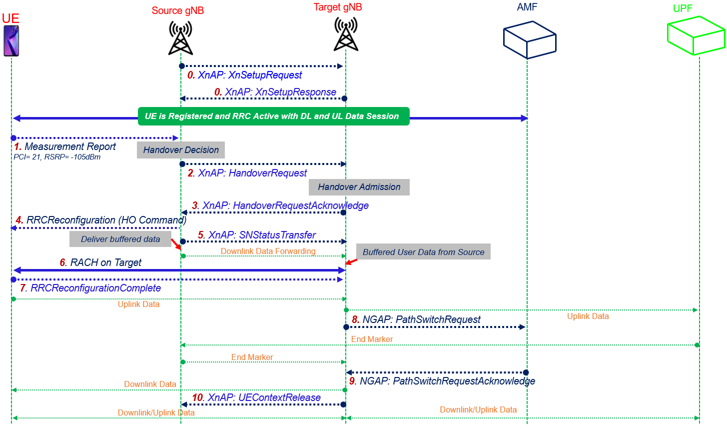
- Step#0: The Source and Target gNB have active Xn connection and the UE is in RRC_CONNECTED, sending and receiving uplink and downlink data at the source gNB and moving toward the Target gNB
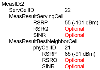
- Step#1-MeasurementReport: The UE sends a MeasurementReport message to the source gNB#1 including the serving cell and neighboring cell signal strength.
- Step#1.1: Based on the measurement report and other information e.g. cell load and taking into account UE mobility restrictions and radio capabilities, the source gNB decides to hand over the UE and selects the handover target gNB
- Step#2-XnAP Handover Request:The source gNB sends the XnAP Handover Request message to the target gNB over the Xn interface. The message caries the transparent RRC container with the Handover Preparation Information RRC message along with the target cell ID, list of PDU sessions, and other information
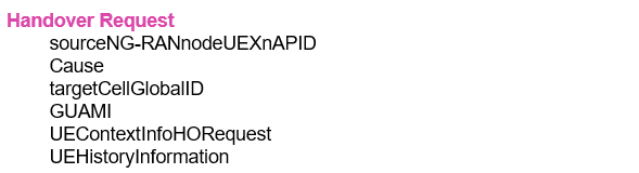
- Step#2-1: The target gNB allocates the resources for the UE while taking into account the information received in the RRC container in step#2
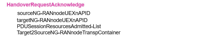
- Step#3-XnAP Handover Acknowledge: If the target gNB decides to admit the handover, it sends the Handover Request Acknowledge message to the source gNB, which includes a transparent container to be sent to the UE as an RRC message to perform the handover and the lists of admitted and not admitted PDU sessions. This completes the handover preparation stage.
- Step#4-RRCReconfiguration: The source gNB triggers the handover by sending the RRCReconfiguration message to the UE, containing the information required to access the target cell received in step#3 at least the target cell ID, the new C-RNTI, and the target gNB security algorithm identifiers for the selected security algorithms.
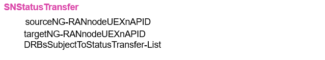
- Step#5-SN Status Transfer: The source gNB sends the SN Status Transfer message to the target gNB to transfer the uplink and downlink PDCP SN and Hyper Frame Number (HFN) status. Source gNB start buffering the DL data coming from UPF and forward to Target gNB.
- Step#6–RACH on Target: A Random Access procedure is performed at the target gNB, considering the information recieved in step#4 as part of rach-ConfigDedicated
- Step#7-RRCReconfigurationComplete: After the UE has successfully connected to the target cell, it completes the handover procedure by sending the RRCReconfigurationComplete message to target gNB. UE starts Uplink data to Target gNB.
- Step#8-NGAP Path Switch Request: The target gNB sends the NGAP Path Switch Request message to AMF over the NG interface to trigger 5GC to switch the downlink data path toward the target gNB and to establish an NG-C interface instance toward the target gNB. The message also carries the list of PDU sessions to be switched and the list of PDU sessions which failed to set up at the target gNB. UPF sends the End Marker to Source gNB indicating end the data flow to Source gNB and Source gNB sends the End Marker to Target gNB.
- Step#9-NGAP Path Switch Request Acknowledge: 5GC switches the downlink data path toward the target gNB. The AMF confirms the Path Switch Request message with the Path Switch Request Acknowledge NGAP message. The message carries the list of PDU sessions that have been switched and the list of PDU sessions to be released.
- Step#10-XnAP UE Conext Release: Upon reception of the NGAP Path Switch Request Acknowledge message from the AMF, the target gNB sends the XnAP UE Context Release message to the source gNB, which can then release resources associated with the UE.

In some cases, the UE needs to initiate a mobility Registration procedure after the handover is completed, e.g., if the handover resulted in that the UE moved outside its Registration Area.
Reference
- 3GPP TS 38 300- 5G NR Overall description Stage-2
- 3GPP TS 38.401 – 5G NG-RAN Architecture Description
- 3GPP TS 38.412 – 5G NG-RAN NG signalling transport
- 3GPP TS 38.422 – 5G NG-RAN Xn signalling transport
Related Post
- 5G Standalone Mode Registration-Attach Call Flow
- 5G RAN and 5GC Network Slice Signaling
- 5G NR HO Setup: Handover Testing in Cabled Setup
- 5G SA N2-NGAP Handover Call flow