5G RAN and 5GC Network Slice Signaling
5G System Network Slicing
Network Slicing is considered as one of the key feature by 3GPP in 5G. A network slice can be looked as a logical end-to-end network that can be dynamically created. A UE may access to multiple slices over the same gNB. Each slice may serve a particular service type with agreed upon Service-level Agreement (SLA).
Network Slicing Pointers:
-
- A Network Slice is defined within a PLMN and includes the 5G Core and 5G RAN Network Control Plane and User Plane Network
- Identification of a Network Slice is done via the Single Network Slice Selection Assistance Information (S-NSSAI) where NSSAI is a collection of S-NSSAIs
- Currently 3GPP allows up to eight (8) S-NSSAIs in the NSSAI sent in signaling messages between the UE and the Network, means a single UE may be served by at most eight Network Slices at a time
- S-NSSAI signaled by the UE to the network, assists the network in selecting a particular Network Slice instance.
- TS 23.501 defines Network Function, Slice, and Slice Instance in terms of Network Slicing
- Network Function: A 3GPP adopted or 3GPP defined processing function in a network, which has defined functional behavior and 3GPP defined interfaces. (Note: A network function can be implemented either as a network element on a dedicated hardware, as a software instance running on a dedicated hardware, or as a virtualized function instantiated on an appropriate platform, e.g. on a cloud infrastructure.)
- Network Slice: A logical network that provides specific network capabilities and network characteristics.
- Network Slice instance: A set of Network Function instances and the required resources (e.g. compute, storage and networking resources) which form a deployed Network Slice.
- Network Slicing can be classified into hard and soft slicing. In, hard slicing network slices must be completely isolated from each other where as in soft slicing network slices may share certain network resources.
Slice Identity Management: S-NSSAI is an identifier for a Network Slice across the 5GC, 5G-RAN and the UE. The S-NSSAI may be associated with a PLMN (e.g., PLMN ID) and have network-specific values or have standard values. A S-NSSAI is used by the UE in access network in the PLMN that the S-NSSAI is associated with. A S-NSSAI is Consist of Slice/Service type (SST) and Slice Differentiator (SD).
-
-
- SST: It refers to the expected Network Slice behavior in terms of features and services
- Slice Differentiator (SD): It is an optional information that complements the Slice/Service type(s) to differentiate amongst multiple Network Slices of the same Slice/Service type.
-
SST ID is Mandatory and its length is 8 bits where as SD is Optional SD to differentiates slices with same SST and having a total length of 24 bits. Standardized S-NSSAI has only SST and no SD, while non-standard S-NSSAI can be defined as either SST alone (Non-standard) or SST + SD.
- Standardized SST
- These standardized values of SST address the three main use cases (eMBB, URLCC and mMTC) for 5G. As SST length is 8 bits so it can provides 2^8= 256 SST values. 3GPP has reserved values O to 127 for standardized SST. Non-standardized values can also be used for the SST. Non-standardized values allow operators to introduce Network Slices which support their own specific service requirements. 3GPP has reserved values 128 to 255 for non-standardized SST.

- Types of NSSAIs
- Subscribed S-NSSAIs: It is stored in the UDM and 5GC uses this as a default when the UE doesn’t send a Requested NSSAI
- Configured NSSAI: The PLMN may configure a UE with 1 or more configured NSSAIs, UE uses this as its default NSSAI. It could be the same as the Subscribed S-NSSAIs. Up to 16 S-NSSAI can be included within a Configured NSSAI. The AMF uses the
NAS: Registration Accept or NAS: Configuration Update Command messages to signal the Configured NSSAI to the UE - Allowed NSSAI: The value assigned by the 5GC & valid in a Registration Area or the PLMN over a given access type.
- There can be a maximum of 8 Network Slices within an Allowed NSSAI, i.e. a UE can be served by a maximum of 8 Network Slices
- Using all 8 Network Slices would require the UE to establish 8 PDU Sessions.
- Similar to the Configured NSSAI, the AMF uses the NAS Registration Accept or NAS Configuration Update Command messages to signal the Allowed NSSAI to the UE.
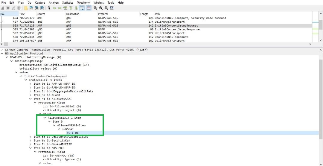
- The Allowed NSSAI is also signaled to gNB using the NGAP Initial Context Setup Request message. The Base Station can use this information when allocating resources for the UE
- Requested NSSAI: It can be either Configured or Allowed NSSAI or a combination.
- UE sends requested NSSAI in both RRC Setup Complete and NAS Registration Request
- gNB uses this for AMF selection and provisional handling before getting Allowed NSSAI
- 5GC use this for slice selection, validation etc., and returns the Allowed NSSAI
- Rejected NSSAI: It can be rejected in the Registration Area (or) for the entire PLMN. UE shouldn’t attempt this NSSAI again in that RA or in the PLMN.
Following Call flow depicts the signaling procedure involves network slices
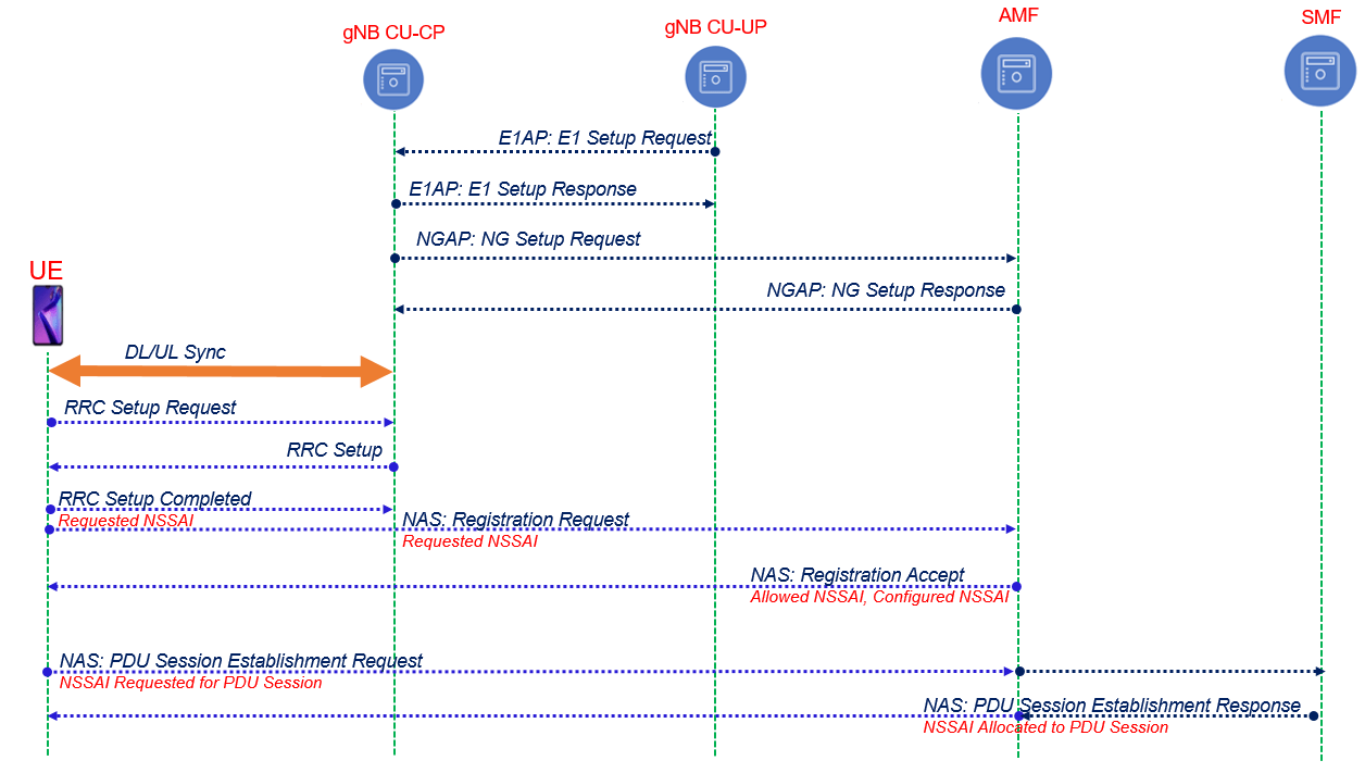
RAN Slice & AMF Selection
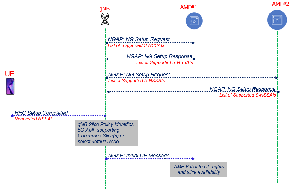
- During NG Setup with AMF-1 & AMF-2, gNB and AMFs exchange their supported NSSAI lists via NG Setup Request and NG Setup Response
- gNB —> NSSAIs per Tracking Area Code (TAC)
- AMF —> NSSAIs in the PLMN
- In the RRC Setup Complete message, UE optionally provides the Requested NSSAI along with the PDU session to be established. Provisional RAN slice selection & AMF selection done based on this
- gNB forwards the NAS Registration Request to the selected AMF instance and AMF validates the Requested NSSAI using Subscribed NSSAI
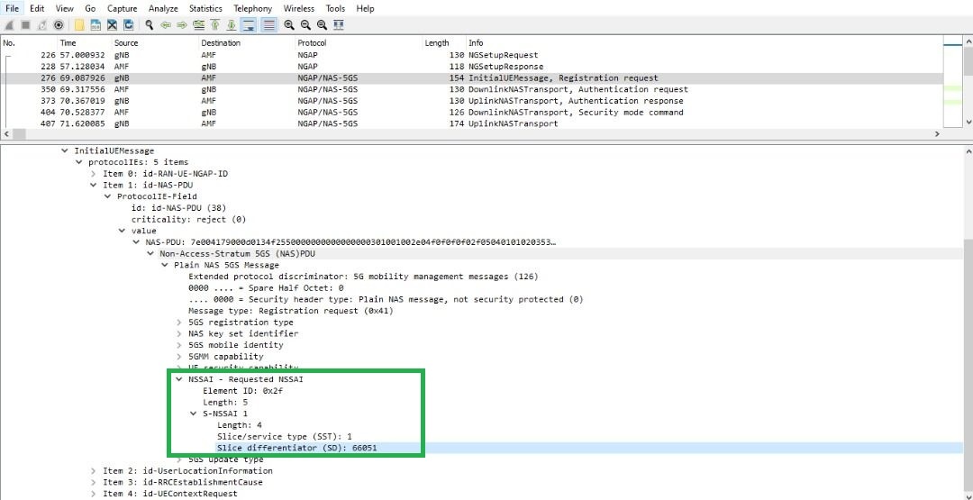
NGAP Signaling for Slice
- Requested NSSAI with Initial UE message/Registration Request
- Allowed NSSAI within Initial Context Setup Request Message
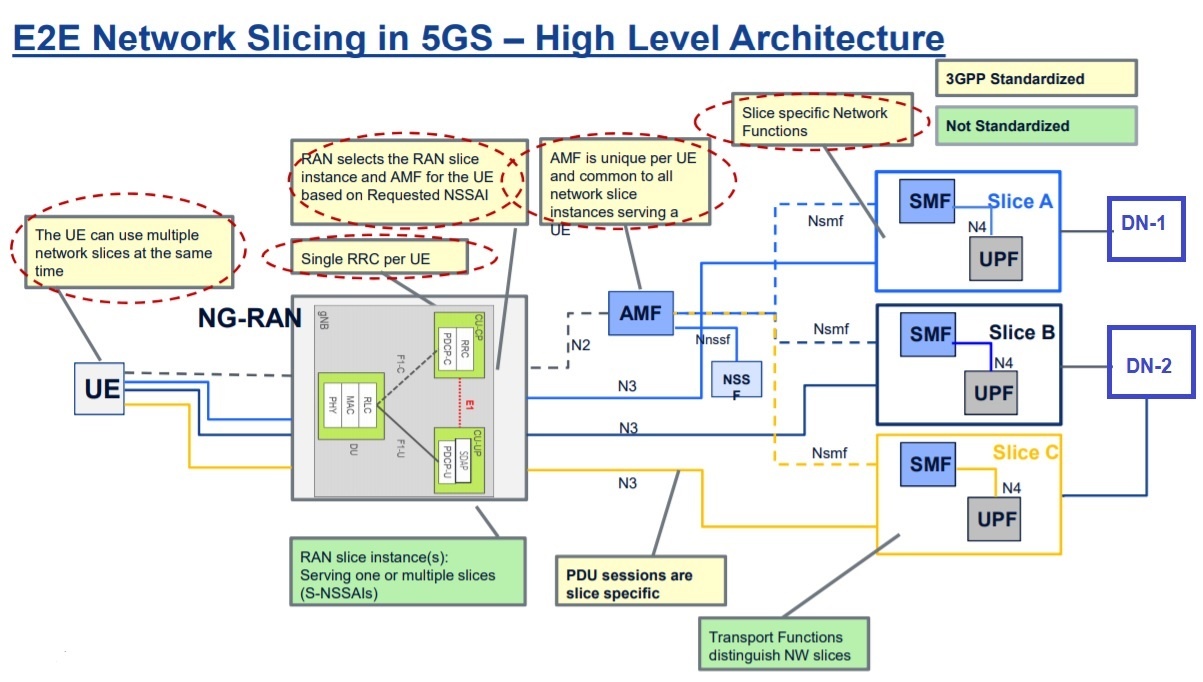
E2E Network Slicing in 5GS – High Level Architecture
Slice Allocation in 5GS Example:
References
- 3GPP TS 23.501: “System Architecture for the 5G System”
- 3GPP TR 28.801: “Study on management and orchestration of network slicing for next generation network”
Related Post:
- NFV Management and Orchestration [MANO] key and performance indicators [KPIs]
- Network Function Virtualization (NFV)
- Virtual Network Function (VNF) Definition, Architecture and Design
- Virtual Network’s Most Common Definitions
- Open Stack, its components and deployment models
- Open Stack Undercloud and Overcloud

