


5G CORESET
In 5G NR, CORESET is known as Control Resource Set. It is a set of physical resources within a specific area in Downlink Resource Grid and used to carry PDCCH (DCI). NR PDCCHs are specifically designed to transmit in a configurable control resource set (CORESET).
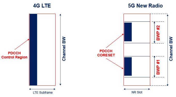
A CORESET is analogous to the control region in LTE but is generalized in the sense that the set of RBs and the set of OFDM symbols in which it is located are configurable with the corresponding PDCCH search spaces. Such configuration flexibilities of control regions including time, frequency, numerologies, and operating points enable NR to address a wide range of use cases.
In LTE control region, the PDCCH is allocated across entire system bandwidth but NR PDCCH is transmit in specifically designed CORESET region to a specific region in frequency domain as shown in below picture.

Frequency allocation in a CORESET configuration can be contiguous or non-contiguous. CORESET configuration in time spans 1-3 consecutive OFDM symbols. The REs in a CORESET are organized in RE groups (REGs). Each REG consists of the 12 REs of one OFDM symbol in one RB. A PDCCH is confined to one CORESET and transmitted with its own demodulation reference signal (DMRS) enabling UE-specific beamforming of the control channel. A PDCCH is carried by 1, 2, 4, 8 or 16 control channel elements (CCEs) to accommodate different DCI payload size or different coding rates. Each CCE consists of 6 REGs. The CCE-to-REG mapping for a CORESET can be interleaved (for frequency diversity) or non-interleaved (for localized beam-forming).
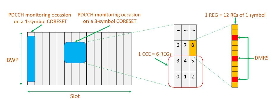

A UE is configured to blindly monitor a number of PDCCH candidates of different DCI formats and different aggregation levels. The blind decoding processing has an associated UE complexity cost but is required to provide flexible scheduling and handling of different DCI formats with lower overhead.
CORESET Characteristics
- NR Control resource set is analogous to LTE PDCCH Control Region
- Two Types Common CORESET and UE Specific CORESET
- Max 3 CORESET can be configured for active downlink BWP including common and UE specific
- A Serving cell can have upto four BWPs and each can have 3 CORESET as in total 12 CORESET
- Each CORESET can be identified by an index with range 0-11 named as controlResourceSetId
- The controlResourceSetId is unique among the BWPs of a Serving Cell
- A special CORESET with index 0 (CORESET 0) is defined, which is configured using a four-bit information
element in the master information block (MIB) with respect to the cell-defining synchronization signal and physical broadcast channel (PBCH) block (SSB). - CORESETs are active only when their associated BWP is active, with the exception of CORESET 0, which is associated with the initial BWP (BWP with index 0)
- In frequency domain CORESETs are configured in units of six PRBs on a six PRB frequency grid
- In time domain CORESETs are configured One, Two, or Three consecutive OFDM symbols
CORESET Parameters
- Resource Element (RE): RE is the smallest unit within the 5G NR resource grid consist of one subcarrier in frequency domain and one OFDM symbol in time domain
- Resource Element Group (REG): One REG is one resource block i.e. 12 REs in frequency domain and one OFDM symbol in time domain
- REG Bundles: One REG bundle is made up of multiple REGs. The bundle size is specified by the parameter ‘L’ indicated with RRC signal parameter reg-bundle-size
- Control Channel Element(CCE): A CCE is a combination of multiple REGs. The number REG bundles within a CCE varies
- Aggregation Level: Aggregation Level indicates the number of CCEs allocated for a PDCCH. Aggregation Level and the number of allocated CCE is defined in following table.
| Aggregation Level | Number of CCEs |
| 1 | 1 |
| 2 | 2 |
| 4 | 4 |
| 8 | 8 |
| 16 | 16 |
How does a CORESET work for UE ?
In LTE, the frequency domain of the control region is always same as the total system bandwidth, so no parameter is required to define the frequency domain region for LTE control region. Time domain region can be {1,2,3} which is determined by PCFICH. However, in NR both frequency region and time domain region can be defined by RRC signaling.
| Parameter | Description |
| NRBCORESET | Number of RBs in frequency domain in a CORESET. Determined by RRC Parameter CORESET-freq-dom |
| NSymbCORESET | Number of symbols in time domain in a CORESET. Determined by RRC Parameter CORESET-time-dur. This can be 1 or 2 or 3, but 3 is possible only when DL-DMRS-typeA-pos = 3 |
| NREGCORESET | Number of REGs in a CORESET |
| L | REG Bundle Size, set by CORESET-REG-bundle-size |
The RRC signaling message parameters defining the CORESET as per 3GPP specification 38.331 is shown below.


- controlResourceSetId : It is corresponds to Layer 1 parameter ‘CORESET-ID’. Value 0 identifies the common CORESET configured in MIB and in ServingCellConfigCommon. Values 1..maxNrofControlResourceSets-1 identify CORESETs configured by dedicated signalling. The controlResourceSetId is unique among the BWPs of a ServingCell.
- frequencyDomainResources: Frequency domain resources defines the resource blocks within BWP assigned to UE. It is correspond to Layer 1 parameter ‘CORESET-freq-dom’.
- Each bit corresponds a group of 6 RBs, the grouping starts from PRB 0, which is fully contained in the bandwidth part within which the CORESET is configured
- The most significant bit corresponds to the group of lowest frequency which is fully contained in the bandwidth part within which the CORESET is configured, each next subsequent lower significance bit corresponds to the next lowest frequency group fully contained within the bandwidth part within which the CORESET is configured, if any
- Bits corresponding to a group not fully contained within the bandwidth part within which the CORESET is configured are set to zero.
- duration : It is corresponds to layer 1 parameter ‘CORESET-time-duration’, defines contiguous time duration in number of symbols for CORESET
- cce-reg-MappingType :It provides the choice of mapping methods for CCE to REG
- reg-BundleSize : It is corresponds to L1 parameter ‘CORESET-REG-bundle-size’ and provides number of REGs within a REG Bundle
- interleaveSize : Corresponds to L1 parameter ‘CORESET-interleaver-size’.
- shiftIndex : Corresponds to CORESET-shift-index. If this parameter is absent then UE applies the value of physical cell ID configured for the serving cell
- precoderGranularity: It is correspond to Layer 1 parameter ‘CORESET-precoder-granuality, precoder granularity is defined in frequency domain
- tci-StatesPDCCH : Reference to a configured TCI State providing QCL configuration/indication for PDCCH
- tci-PresentInDCI : Corresponds to Layer 1 parameter ‘TCI-PresentInDCI’. This field indicates if TCI field is present or not present in DL-related DCI.
- pdcch-DMRS-ScramblingID : PDCCH DMRS scrambling initialization parameter, Corrosponds to layer 1 parameter “PDCCH-DMRS-scrambling-ID. When the field is absent then UE applies the value of physical cell ID configured for the serving cell
Mapping of PDCCH to CORESET
A DCI of AL 𝐿 comprises 𝐿 continuously numbered CCEs, and the CCEs are mapped on a number of REGs in a CORESET. NR supports distributed and localized resource allocation for a DCI in a CORESET. This is done by configuring interleaved or non-interleaved CCE-to-REG mapping for each CORESET. For interleaved CCE-to-REG mapping, REG bundles constituting the CCEs for a PDCCH are distributed in the frequency domain in units of REG bundles as shown in figure below.
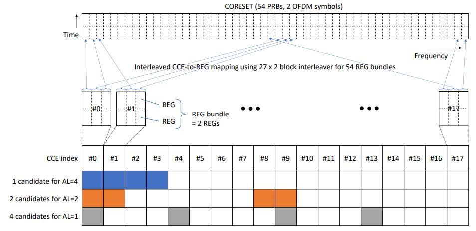

A REG bundle is a set of indivisible resources consisting of neighboring REGs. A REG bundle spans across all OFDM
symbols for the given CORESET. Therefore, interleaved CCEto-REG mapping can enable both a time domain processing gain and frequency domain diversity. Interleaved CCE-to-REG mapping can be visualized as a process for which REG bundle indices are continuously filled in an array row-wise first and then read out column-wise. This process is often called block interleaving. By this means, adjacent CCEs for a PDCCH are broken down into scattered REG bundles in the frequency domain. On the other hand, for non-interleaved CCE-to-REG mapping, all CCEs for a DCI with AL L are mapped in consecutive REG bundles of the CORESET.
Once the REGs corresponding to a PDCCH are determined, the modulated symbols of the PDCCH are mapped to the REs of the determined REGs in the frequency domain first and the time domain second, i.e. in increasing order of the RE index and symbol index, respectively.
NR supports both wideband and narrowband precoding for the PDCCH. In wideband precoding, PDCCH DMRSs are transmitted in all contiguous REGs of a CORESET carrying the PDCCH using the same precoder. On the other hand, in the narrowband precoding, PDCCH DMRSs are transmitted only in the REG bundles actually used for the PDCCH transmission, and precoding is constant only within the REG bundle. The former can maximize the frequency domain processing gain and the latter can take advantage of frequency dependent beamforming gain. Since the same precoding is applied to payload and the corresponding DMRS, precoding is transparent to the UE.
Reference:
- 3GPP TS 38.211 5G; NR; Physical channels and modulation
- 3GPP TS 38.331 5G; NR; Radio Resource Control (RRC); Protocol specification
- 5G New Radio: Unveiling the Essentials of the Next Generation Wireless Access Technology
- Understanding the Heart of the 5G Air Interface: An Overview of Physical Downlink Control Channel for 5G New Radio (NR)