5G EPS Fallback | 5G to 4G Handover
5G EPS Fallback
A Network Operator providing 5G NR and 4G LTE service, but it may not be possible to have 5G coverage everywhere and at some point when 5G coverage or service not available to 5G system (5GS) may attempt to fallback the RAT to 4G Evolved Packet System (4G-EPS). EPS Fallback can be defined as the mobility procedure where network trigger the procedure for UE to change Radio Access from 5G to 4G.
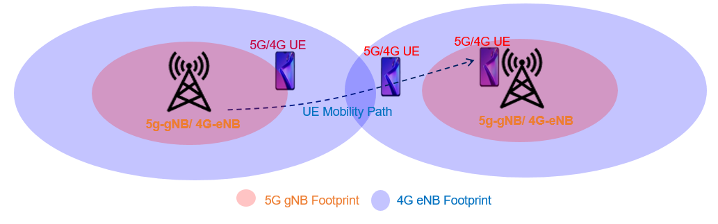
We can see following fiugre showing the mobility profile for a UE performing mobility 5G to 4G, 4G to 4G and 4G to 5G. Here we can see the gNB and eNB are co-located and gNB is operating on higher frequency band with lower coverage footprint and eNB operating on lower frequency band with larger coverage footprint.
Types of EPS Fallback
Considering the 5G and 4G interworking, the EPS Fallback can be supported using following two methods:
- Method #1: 5G to 4G Inter-RAT Handover
- In this method, N26 interface between AMF and MME use Forward Relocation procedure and session management context and user plane tunnels in core network are exchanged over from SMF/UPM to MME/S-GW.
- Method #2: 5G to 4G Release with Redirection
- In this method, 5G radio connection is released with the 5G RRC Release instructing UE to reselect to a 4G cell where a new radio connection can be started for the VoLTE call. In this case the UE context is transferred from the AMF to the MME over the N26 interface.
The choice of method used for EPS fallback depends on UE capability and 5G Core Network Capability.
5G to 4G Inter RAT Type
- HO based on coverage (NR > LTE)
- When a UE establishes a radio bearer, the gNB sends the UE the measurement configuration message containing A2 measurement configurations, based on which the UE performs measurements. If the gNB receives A2 measurement reports, it delivers inter-RAT B2 measurement and A1 measurement configurations. When UE reports event B2, gNB can trigger the inter-RAT HO, After receiving A1 measurement reports, the gNodeB stops inter-RAT handover measurements.
- HO based on Voice Service (NR > LTE)
- When the UE establishes a Voice Flow (5QI=1) and the bearer policy of the voice service is carried on the LTE network, the gNodeB rejects the setup of the Voice Flow and instructs the UE to perform B1 measurements. After receiving B1 measurement reports from the UE, the gNB finds the qualified LTE cell according to the PCI carried in the B1 measurement reports.
If you want to read about 5G Measurement Events in details is available here.
Inter-RAT 5G to 4G Handover Signalling
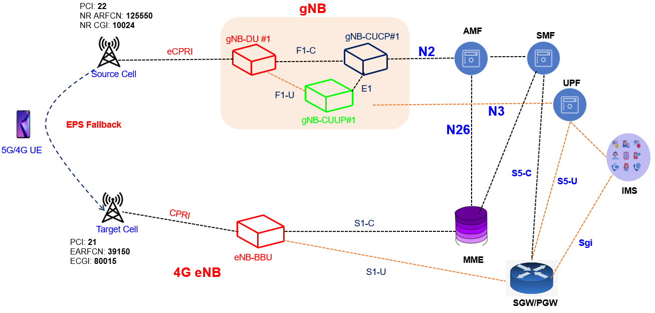
Following figure show the network overview for Inter-RAT handover. Here we can see 5GS includes 5G RAN (Radio, DU, CU) connected to 5GC and 4G EPS includes 4G RAN (Radio, BBU) connected to 4G EPC. Individual 5G and 4G Core nodes also maintain the contol plane and user plane connectivity e.g. control plane AMF connectes to MME via N26 Interface and UPF connects to gateways via S5-U interface.
Initial, UE is connected with 5G Cell and having active data session and observe A2 measurement event indicating the 5G serving cell is below then the defined thresholds. gNB may configure B2 event with meas object defining 4G EARFCN to find out a suitable 4G cell. UE start looking for 4G cell on define EARFCN e.g. 39150 and report the PCI as soon as B2 event is satisfied.
- Note: Inter RAT handover can be triggered based on B1 or B2 event, it purely depends on the vendor implementation
Handover Call Flow
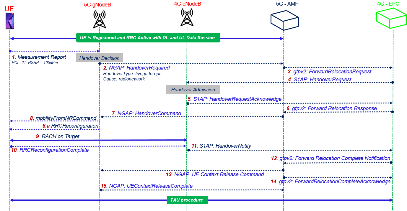
- Step#1 RRC: MeasurementReport: The UE sends a MeasurementReport message to the source gNB including the serving cell and neighboring 4G cell signal strength as indicated below.

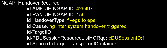
- Step#2 NGAP: HandoverRequired: After receiving the measurement report, the serving gNB check the reported 4G Cell PCI in neighbor relation table (NRT) and if nieghbor is available it can initiate the HandoverRequired message over N2 interface using NGAP protocol towards AMF. It includes UE identities (AMF-UE-NGAP-ID, RAN-UE-NGAP-ID), Handover Type, Handover Cause, Target Cell ID, PDU session to be handover and Source to Target Transparent Container having the full UE context and capabilities.
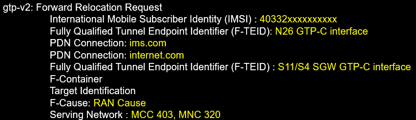
- Step#3 gtp-v2: Forward Relocation Request: The serving AMF sent Forward Relocation Request to Target MME over the N26 interface using the gtp protocol. It includes the IMSI, TEIDs, UE PDN information, Target Information and cause.
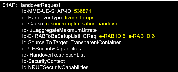
- Step#4 S1AP: HandoverRequest: The taget MME sends the Handover Request to target eNB including MME-UE-S1AP-ID, Handover Type, Hanodver Cause, E-RAB information, Source to Target Transparent Container, UE Capabilities and UE security context.
- Step#5 S1AP: HandoverRequestAcknowledge: After receiveing the Handover request from MME, target 4G eNB start the UE admission procedure, if the resources are available then eNB and respond with HandoverRequestAcknowledgement including UE IDs (MME-UE-S1AP, eNB-UE-S1AP), list of admitted e-RABs and Target to Source Transport Container. If eNB does have enough resousrce to admit the UE, it can send Handover Failure with appropriate casue mentioning no resource available.

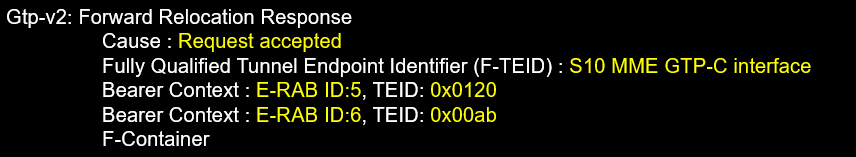
- Step#6: gtpv2: Forward Relocation Response: After Handover Acknownledge, the MME send Forward Relocation Response to 5G AMF over N26 interface including the TEIDs and UE Bearer Context.
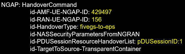
- Step#7: NGAP: HandoverCommand: AMF sends a Handover Command to source gNB. This message includes, information received in step#5 . The source gNB can now send a Handover Command to the UE in step#8 as RRC message mobilityFromNRCommand. After receiving the Handover Command, the UE will leave the source cell and start the connection towards the target 4G cell.
- Step#8: mobilityFromNRCommand: 5G gNB send it as the handover command to UE, it includes targetRAT-Type eutra, targetRAT Container and nas-SecurityParamFromNR information.
- Step#8.a: RRCReconfiguration: UE RRC decodes target RAT container as RRCReconfiguration which have mobilityControlInfo indicating all 4G Target cell information like carrier Bandwidth, UE-CRNTI as target, RACH config and other channel information.
- Step#9 RACH: A Random Access procedure is performed at the target eNB, considering the information recieved in step#8.a as part of rach-ConfigCommon or rach-ConfigDedicated. rach-ConfigCommon used when eNB is not using dedicated premable for Handover and rach-ConfigDedicated is used when eNB is using dedicated contention free RACH.
- Step#10 RRCReconfigurationComplete: After the UE has successfully connected to the target 4G cell, it completes the handover procedure by sending the RRCReconfigurationComplete message to target eNB. UE starts Uplink data to Target eNB.
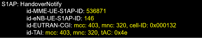
- Step#11 S1AP: HandoverNotify: Once UE has a successful RACH at 4G eNB and RRCReconfigurationComeplete is done then eNB inform the MME with HandoverNotify indicating the HO is successful. It includes UE IDs (MME-UE-S1AP and eNB-UE-S1AP), Target Cell ECGI and Tracking Area Inforamtion.
- Step#12 gtpv2: ForwardRelocationCompleteNotification: As soon as MME recieved Handover Notify from Target eNB, the MME informs the AMF with Forward Relocation Complete Notification over N26 interface indicated UE reached to 4G Target Cell and AMF can proceed with UE context clean-up at 5G System.

- Step#13 NGAP: UEContextReleaseCommand: By sending UEContextReleaseCommand AMF will instruct source gNB to release the resources related to this UE. AMF in the message includes UE-NGAP-IDs to identify the UE context and cause indicating successful handover

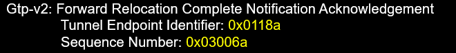
- Step#14 gtpv2:ForwardRelocationCompleteNotificationAcknowledge: AMF send acknowledgement for Relocation Complete Notifcation as soon as it start UE context cleanup procedure at 5G RAN and 5G Core.
- Step#15 NGAP:UEContextReleaseComplete: Source gNB sends UEConextReleaseComplete upon successful deleting the UE context and release all the associated resource for the UE.

At last when UE successful handover to 4G Cell, it does perform the Tracking Area Update Procedure to update its current serveing Tracking Area.
References:
- 3GPP TS 38 300- 5G NR Overall description Stage-2
- 3GPP TS 38.401 – 5G NG-RAN Architecture Description
- 3GPP TS 38.412 – 5G NG-RAN NG signalling transport
Related Posts:
- 5G SA Handover – Inter gNB-DU and Intra gNB-CU Handover
- 5G SA Xn Handover Call flow
- 5G SA N2-NGAP Handover Call flow
- 5G N26 Interface – 5G to 4G Interworking
- 5G AMF – Access and Mobility Management Function
- 5G Service Based Architecture