Carrier Aggregation Explained
Carrier Aggregation (CA) is a key feature of LTE-Advanced (4G), introduced in Release 10 of 3GPP standards. Carrier Aggregation allows UE to combine two or more carrier frequencies to increase bandwidth, thereby maximizing downlink and uplink throughput.
Carrier Aggregation is applicable to both Frequency Division Duplex (FDD) and Time Division Duplex (TDD).In the case of TDD, the uplink-downlink subframe configuration must be consistent across all component carriers. This enables higher data rates and better utilization of available spectrum resources.
Carrier Aggregation Key Features in Release 10
- With CA we can achieves downlink speeds of up to 1 Gbps and uplink speeds of up to 500 Mbps.
- CA is backward compatibility with Release 8 and Release 9.
- Compatible with both FDD and TDD
- Carriers are called Component carriers (CC) and can have bandwidths of 1.4, 3, 5, 10, 15, or 20 MHz.
- It can supports up to 5 aggregated component carriers, enabling a maximum aggregated BW of 100MHz.
- Contiguous CCs are spaced by multiples of 300 kHz, while non-contiguous CCs are separated by one or more frequency gaps.
Components in Carrier Aggregation
- Primary Component Carrier (PCC): The main carrier used for UE to connect to the network. It handles essential signaling and control functions.
- Secondary Component Carriers (SCCs): It is additional carriers aggregated with the PCC to enhance data throughput.
Types of Carrier Aggregation

- Intra-Band Contiguous:
- In Intra Band Contiguous CA aggregates component carriers (CCs) within the same frequency band and ensures they are adjacent to each other.
- Intra-Band Non-Contiguous:
- Intra-Band Non-Contiguous CA aggregates CCs within the same frequency band but they are not adjacent.
- Inter-Band Non-Contiguous:
- Inter Band Non-Contiguous CA aggregates CCs from different frequency bands. This type of CA is widely used because spectrum is often distributed across multiple bands.
CA Bands Notation
The Carrier Aggregation (CA) band notation includes the following elements:
- “CA_” Prefix: Indicates that the notation refers to a Carrier Aggregation configuration.
- Band Numbers: Specifies the frequency bands being aggregated, using standardized LTE band numbers (e.g., Band 1, Band 3, Band 40).
- Combination Style: Multiple bands are separated by a
+sign. - Bandwidth Class Indicators: In some notations, bandwidth classes may be included, indicating the size of each aggregated carrier: Classes: Denoted by a letter (e.g., A, B, C), where: A = ≤20 MHz, B = 20–40 MHz, C = 40–60 MHz.

CA Bands Notation Examples
- CA_1C: Carrier Aggregation within Band 1, contiguous (the “C” indicates contiguous carriers).
- CA_1A-3A: Aggregates Band 1 and Band 3, where “A” indicates the primary component carrier (PCC)
- CA_1A+3A+7A: Aggregates Band 1, Band 3, and Band 7
- CA_1A-3B: Aggregates Band 1 (20 MHz) and Band 3 (up to 40 MHz).
- CA_1A+3A+7A: Aggregates Band 1, Band 3, and Band 7.
- CA_1A+3A+7A-28A: Includes an additional Band 28 carrier in a 4CC (Four Carrier Component) aggregation.
Carrier Aggregation RRC Aspects
Given the flexibility of CA, the E-UTRAN must be informed of the details of the UE’s support for CA. This is accomplished via the RRC UE Capability Transfer procedure during the establishment of an EPS bearer. The CA-related information sent by the UE related to this procedure is summarized below:
- UE category – CA support is implied by UE categories 6, 7, and 8. However it does not indicate the support for a particular carrier aggregation configuration, which is signalled separately.
- Cross-carrier scheduling support – Indicates that the UE can receive scheduling orders regarding SCells from the PCell.
- Simultaneous PUCCH and PUSCH tx support – For CA-capable UEs, implies that the UE can support simultaneous PUCCH and PUSCH transmission on different CCs.
- Multi-cluster PUSCH within a CC support – Indicates baseband (non-band-specific) support for multi-cluster PUSCH transmission within CCs
- Non-contiguous uplink resource allocation within a CC support – Indicates RF (band specific) support for non-contiguous uplink resource allocations within CCs.
- Supported band combinations – Indicates the specific frequency band and channel bandwidth configurations that the UE can utilize in support of CA.
- Event A6 reporting support – Indicates that the UE is able to report Event A6, which occurs when a neighbour PCell becomes stronger than a serving SCell by an offset.
- SCell addition during handover to E-UTRA support – Indicates that the UE can support E-UTRAN inbound inter-radio access technology (IRAT) handover directly into CA mode.
- Periodic SRS transmission on all CCs support – Indicates that the UE can transmit periodic
SRSs on all SCells.
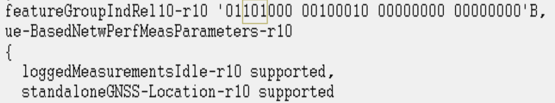
Feature Group Indicator
FGI bits are typically represented as part of a larger bitmap, with specific bits dedicated to CA features.
- FGI Bit 28: Indicates the support for Carrier Aggregation.
- FGI Bits 45–48: Extend CA capabilities and add support for features like inter-band aggregation.
- FGI Bit 111: Measurement of event A6 is supported or not.
- FGI Bit 112: Secondary cell to be added or not during handover.
- FGI Bit 113:Cross-carrier scheduling is enabled or not
Following is QXDM logs snapshot showing FGI related to Carrier Aggregation.
Related Post
- 3GPP Release 10
- LTE FDD System Capacity and Throughput Calculations
- LTE TDD Special Subframe and Its significance for Cell Size
- Dual Connectivity (DC) Definition, Protocol Architecture, DC and CA Comparison