5G NR SSB Positioning – Time and Frequency Resources
5G Synchronization Signal Block (SSB)
In 5G NR, Synchronization Signal Block (SSB) includes PSS, SSS and PBCH and its location compared to LTE is completed different. In LTE, Sync signal position is straight forward located around DC carrier (Center 6 PRBS/72 subcarriers) but in 5G Sync signals are positioned on the Bandwidth part is not fixed and can be located any where across the Carrier Bandwidth.
Here we can taken an example for 5G NR band n78 (TD3500) with FR1 and tried to put together how Time Domain & Frequency Domain resources are allocated for SSB and how positioning of SSB on CBW is determined.
SSB Time Domain Resource
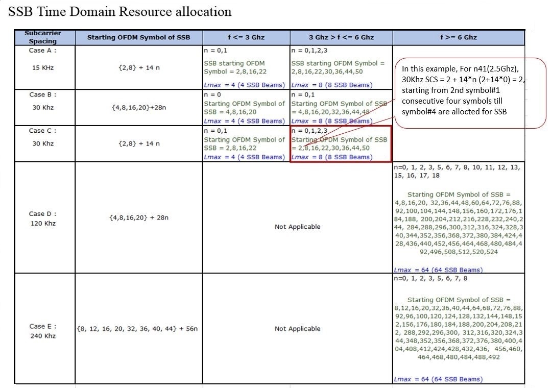
- SS block consists of 4 consecutive OFDM symbols
- The 1st symbol Position is determined by combination of Carrier Bandwidth (CBW) + Sub-carrier spacing (SCS)
- 3GPP specification TS 38.213 provided below table to determines the position of starting OFDM Symbol of each SCS in a CBW.
SSB Frequency Domain Resources
- SSB in frequency domain consist of 240 consecutive Subcarriers numbered in increasing order from 0 to 239 is equal to 20 PRBs
- If ssb-SubcarrierOffset is not provided, SSB is derived from the frequency difference between the SS/PBCH block and Point A.
- In NSA mode operation the location of the SSB is determined by information provided by higher layer in RRC Reconfiguration message, IE’s are highlighted in below snap.
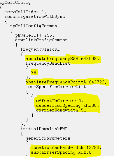
Following information can be extracted from above RRC Message.
- Band = n78 is a TDD band known as TD3500 its frequency range is 3300MHz to 3800 MHz belongs to FR1
- SCS = 30Khz with Carrier Bandwidth= 51 RB’s which is 20 MHz with reference to following figure.

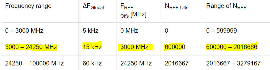
FREF = FREF-Offs + ΔFGlobal (NREF – NREF-Offs) (i)
- absoluteFrequencyPointA: It represents the common reference point A, this reference point is the 0th RB of 273 RBs, which is the center point of RB#0. From above logs absoluteFrequencyPointA= 642722 (NREF)
- absoluteFrequencyPointA= 3000 MHz + 15* (642722 -600000) KHz= 3,640.83 MHz
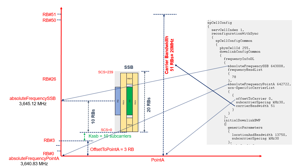
- absoluteFrequencySSB: It represent the center frequency of SSB Block. A SSB block is 20 RBs results 20 * 12 =240 Subcarriers and from above logs snippet absoluteFrequencySSB= 643008 (NREF)
- absoluteFrequencySSB= 3000 MHz + 15* (643008 -600000) KHz= 3,645.12 MHz
- Carrier Center Frequency: The total number of RB’s=51 and Resource Block corresponding to center frequency is 51/2=26
- Center Frequency= absoluteFrequencyPointA + 26 RBs * 12 * Subcarrier Spacing
- Center Frequency= 3,640.83 + 26 * 12 *30 KHz = 3,650.19 MHz
Position of SSB from Point A
- offsetToPointA= It defines the frequency offset between point A and the lowest subcarrier of the RB overlapping with SSB. The unit for RB is expressed as 15KHz for FR1 and 60 KHz for FR2
- Kssb= it defines the frequency of RB#0 of SSB and The unit for RB is expressed as 15KHz for FR1 and 60 KHz for FR2
Frequency offset to SSB from Point A = offsetToPointA + Kssb
- Difference between the SSB center frequency (absoluteFrequencySSB) and point A (absoluteFrequencyPointA)
- 3,645.12 – 3,640.83 = 4290 KHz
- Difference between the Point A and 0th subcarrier RB#0 of SSB
- 4290 – 10 (bottom 10 RB of SSB)* 12 *30 = 690 KHz
- Calculating No. of RBs= 690/180 =3.8
- offsetToPointA = 3
- Kssb = (690 – 3 * 12 *15) / 15 KHz = 10 Subcarriers
- offset to SSB from Point A = offsetToPointA + Kssb = 3 RBs + 10 Subcarrier
Reference
- 3GPP 38 211 5G; NR; Physical Channels and Modulation
Related Posts
- 5G NR Resource Block Definition and RB calculations
- 5G NR Modulation and Coding Scheme (MCS)
- NR-Cell Physical Layer Cell ID
- NR-Primary Synchronization Signal (PSS)