5G NR Cell Search | 5G System Acquisition Procedure
5G Cell Search
Cell search is the procedure by which a UE acquires time and frequency synchronization with a cell and decode the Cell ID of that cell. In 5G NR, Cell search concept is similar to what it is in LTE in terms of decoding Primary Sync Signal (PSS) and Secondary Sync Signal (SSS) to the Physical Cell ID (PCI).
There are 2 methods by which a UE can access a 5G-NR cell.
- Non Stand Alone Mode (NSA) Deployment : EUTRA – NR Dual Connectivity [EN-DC]
- Standalone [SA] Deployment: NR Only Cell
In EN-DC, Cell Search information like frequency (NR-ARFCN), Cell ID, RACH parameters, etc. are provided by network in RRC Reconfiguration message via LTE eNB. The UE can attempt RACH to access the NR cell.
Cell Search Procedure in 5G SA
In Standalone , NR Cell Search procedure follows below steps:
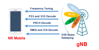
- UE tunes to a specific frequency
- UE tries to detect PSS, SSS signals to acquire frequency and time synchronization
- Once UE successfully detect PSS/SSS, it gains the knowledge about synchronization and Physical cell ID (PCI), now UE is ready to decode PBCH
- Once UE successfully decoded PBCH, it tries to PDCCH and PDSCH for RMSI and OSI
UE scans the frequency band on sync raster based on which frequency band the UE is performing cell search on and is defined by 3GPP 38.104 section 5.4.3.3 to tune specific frequency. The synchronization raster indicates the frequency positions of the synchronization block that can be used by the UE for system acquisition when explicit signaling of the synchronization block position is not present. The synchronization raster and the subcarrier spacing of the synchronization block is depend on separately for each band.
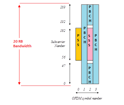
In further step UE decode primary and secondary synchronization signals to get Physical Cell ID [PCI], and PBCH DMRS, located on the synchronization raster. PSS, SSS, and NR-PBCH are transmitted in a Synchronization Signal Block (SS Block). SSB is consist of 4-symbol, 1-symbol PSS, a 1-symbol SSS, and a 2-symbol PBCH.Time synchronization in terms of symbol-level and slot-level and frequency synchronization are realized via PSS/SSS.
NR supports up to 1008 PCIs, twice as many as that of LTE. 336 unique cell-identity groups each group containing three unique and it can be calculated by following formula:
![]()
where
- N (1) ID = Secondary Synchronization Signal (SSS) and its range is from {0, 1….335}
- N (2) ID = Primary Synchronization Signal (PSS) and its range is from {0, 1, 2}
SSBs is transmitted in a batch by forming an SS Burst (one SSB per beam) that is used during beam sweeping by changing beam direction for each SSB transmission. Beam Sweeping mechanism is used by UE to measure and identifies the best beam for a UE.
A collection of SS Bursts is referred to as an SS Burst Set. Both SS Burst and SS Burst Set may contain one or more elements, while the maximum number of SSBs in an SS Burst is frequency-dependent and it can 4 (below 3 GHz), 8 (3 to 6 GHz), or 64 (6 to 52.6 GHz). The periodicity of the SSB is configured by the network, while the default transmission periodicity for initial cell selection, the SS burst set periodicity is default at 20 ms for all frequency range i.e., 2 NR frames. This interval is four times longer than that in LTE (5 ms) and aims at reducing the “always-on” transmission overheads. The frame and slot timings are defined by the identifiers of SBSs and acquired by the UE.
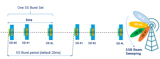
The gNB define multiple candidate positions for SSBs within a radio frame, and this number corresponds to the number of beams radiated in a certain direction. Each SSB can be identified by a unique number called SSB index and identification of which SSB is detected is depend on where UE is located. UE measures the signal strength of Demodulation Reference Signal (PBCH DMRS) of each SSB it detected for a certain period (a period of one SSB Set). From the measurement result, UE can identifies the SSB index with the strongest signal strength. This SSB with the strongest signal strength is the best beam for the UE.
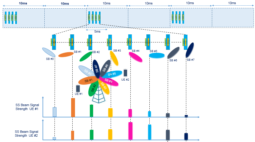
The above picture shows example of two UEs, UE#1 finds the SB# 1 as best and UE#2 find the SB#4 as best beam.
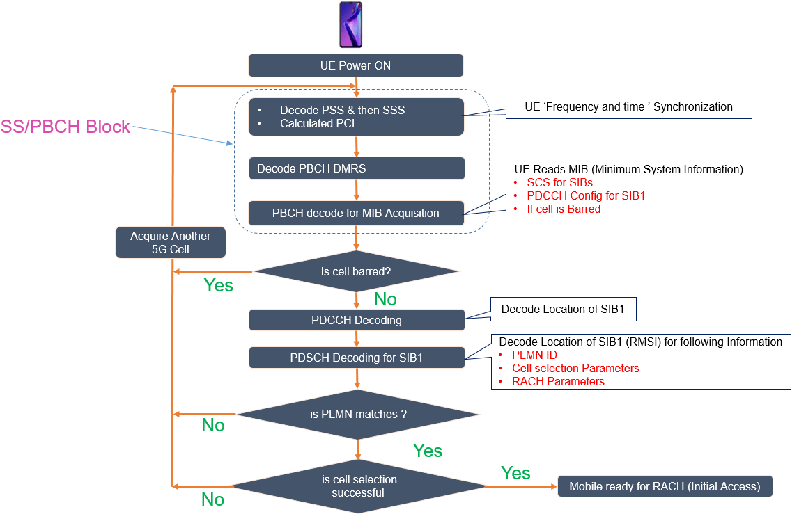
- UE choose the best beam and decode the PBCH MIB contents information such as SFN, SSB index, raster offset, default DL numerology, RMSI configuration, DM-RS location, and cell barring information etc.
- If cell is not barred, UE tries to decode subsequent physical downlink control channels (PDCCH) to get frequency location of PDSCH resources to ready SIB#1 information.
- The configuration of PDCCH for RMSI is provided by PBCH. The COntrol REsource SET (CORESET) configuration for RMSI is associated with a SS block in a SSB burst set. A one-bit information field in PBCH signals the SCS of RMSI, as well as OSI and other messages in random access procedures for initial access.
- UE reads Remaining Minimum System Information from SIB#1 and decode the PLMN ID, cell selection parameters, RACH parameters
- If PLMN ID of network matches with the PLMN ID list available with the UE, then UE runs the cell selection procedure, else the UE acquires another 5G cell and restart the process again
- Another parameter UE tries to validate the qRxmin, if the signal detected by UE satisfy the qRxmin level the cell selection procedure is successful and UE can tries for uplink synchronization with RACH procedure
- If cell selection is not successful then UE tries to acquire another cell and restarts the process again.
Related Post
- NR-Cell Physical Layer Cell ID
- NR-Master Information Block (NR-MIB)
- NR-Primary Synchronization Signal (PSS)
- NR-Secondary Synchronization Signal (SSS)
- 5G NR Reference Signals (DMRS, PTRS, SRS and CSI-RS)
- 5G NR Sounding Reference Signal (NR-SRS)


