

Introduction
FAPI is an interface, which originally meant Femtocell Application Programming Interface defines the interface between MAC-Layer#2 and PHY – Layer#1 for small cells. FAPI is specified by the Small Cell Forum and the original interface defined the interaction between a 3G MAC and PHY (SCF 048), Subsequently a version was defined between a 4G MAC and PHY (SCF 082), and recently the 5G version has been completed (SCF 222).
For each wireless technology FAPI defines a set of control messages for configuring a PHY and a set of messages for exchanging data between MAC and PHY, and indicates the timing constraints of these messages.
Key Pointers
- FAPI means Femtocell Application Programming Interface
- It is an interface between MAC and PHY in Small Cells
- FAPI specification are managed by Small Cell Forum
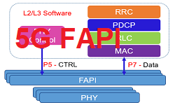
- FAPI specification has defined two Logical interface P5 and P7
- The PHY control plane message are transferred over P5 interface
- The PHY data-plane messages are transferred over P7 interface
FAPI Architecture
The architecture of FAPI is shown in figure below. FAPI is defined between one instance of MAC and one instance of PHY. In scenarios such as CA there will be multiple instances of FAPI, one per carrier. There are two types of PHY configuration messages are defined by the logical interface as P5 and P7. P5 Logical Interface is for PHY control configuration which is semi-static and is being generated by a PHY control entity.


The P7 logical interface is for PHY data plane messages, P7 interface data configuration is generated once per slot and consists of following:
- Slot configuration messages, which include information required by the PHY to encode and decode data
- Downlink data messages to transfer MAC PDUs to the PHY.
- Uplink data messages to transfer MAC PDUs, Uplink Control Information ,Sounding Reference Signal and RACH PDUs from the PHY
FAPI State Machine
To support consistent PHY behavior, FAPI has defined a state machine for the PHY as shown below.


- A PHY starts in IDLE mode, where the MAC can query the PHY’s capabilities using the PARAM message sequence
- A PHY can be moved from IDLE to CONFIGURED state by the MAC initiating the CONFIG message sequence
- A PHY in CONFIGURED state can be configured further, or have its PHY capabilities queried
- A PHY can be moved from CONFIGURED to RUNNING state by the MAC initiating the START message sequence
- A PHY in RUNNING state is transmitting over the air and provides a small cell service
- To stop the small cell the MAC must initiate the STOP message sequence.
Once a PHY is operational the interaction between the MAC and PHY occurs at the periodicity of a slot. Since 5G supports several different subcarrier spacing these per-slot messages can be exchanged every 125 μs, 250 μs, 500 μs, or 1 ms. In fact, if a carrier is supporting several different bandwidth parts, with different subcarrier spacing, then the MAC may be exchanging FAPI messages with the PHY at different periodicities for different BWP.
FAPI reduces this complexity by providing all per-slot control messages in a single downlink control message, DL_TTI.request, and all downlink MAC PDUs in a single downlink data message, TX_Data.request. Similarly, for the uplink there is a single uplink control message, UL_TTI.request, and all similar uplink is grouped together into one message, RX_Data.indication, UCI.indication, SRS.indication, and RACH.indication.
P5 – Control Configuration Procedures
The Control configuration procedures supported by the L1 FAPI over P5 interface are listed below:
- Initialization
- Termination
- Restart
- Reset
- Error notification
These procedures will move the PHY layer through the IDLE, CONFIGURED and RUNNING states
P7 – Data Plane Configuration Procedures
The P7 – Data plance configuration procuedres serve two purposes for subframes procedures. Firstly, they are used to control the DL and UL frame structures. Secondly, they are used to transfer the subframe data between the L2/L3 software and PHY. The procedures supported by the L1 FAPI over P7 interface are listed below:
- Transmission of a 1ms Subframe message
- Synchronization of SFN/SF between the L2/L3 software and PHY
- Transmission of the BCH transport channel
- Transmission of the PCH transport channel
- Transmission of the DLSCH transport channel and reception of ACK/NACK response
- Transmission of the MCH transport channel
- Reception of the RACH transport channel
- Reception of the ULSCH transport channel and transmission of ACK/NACK response
- Reception of the sounding reference signal
- Reception of CQI and RI reporting
- Reception of scheduling request information
Reference:
- SCF082 – nFAPI and FAPI Specifications
Related Posts:
- Open RAN (O-RAN) Reference Architecture
- Open RAN Network Architecture Components
- What is eCPRI, how it contributes to 5G and Open RAN?
- O-RAN Fronthaul Spilt Option 7-2x