


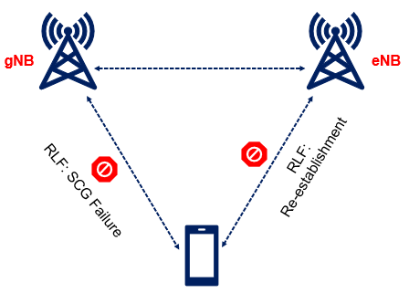
For the purpose of Radio Link Failure (RLF), the UE physical layer monitors the downlink radio link quality of the primary cell for indicating out-of-sync / in-sync status indications to the higher layers. In 5G NSA EN-DC mode, RLF is declared separately for the MCG (E-UTRA LTE Cell) and for the SCG cells (NR). If radio link failure is detected for MCG (LTE eNB), the UE initiates the RRC connection re-establishment procedure, but when RLF is detected for SCG (NR cell) failure, the UE suspends SCG transmissions for all radio bearers and reports the SCG Failure Information to the eNB, instead of triggering re-establishment.

SCG Failure include: SCG RLF, SN change failure, SCG configuration failure only for messages on SRB3 or SCG RRC integrity check failure on SRB3.
UE can trigger the SCG failure in following condition:
- SCG radio link failure.
- Failure of SCG reconfiguration with sync.
- SCG configuration failure for RRC message on SRB3. SRB3 is control plane between UE and gNB.
- SCG Integrity Failure
- Exceeding the maximum uplink transmission timing difference.
SCG Radio Link failure: A UE declares radio link failure on SCG cell if any of the below condition is met
-
- Expiry of T310 in Pscell : If RLF occur because of T310 expiry then UE trigger SCG failure with failureType as t310-Expiry. UE start the T310, upon receiving N310 consecutive “out-of-sync” indications from lower layer and stop this Upon receiving N311 consecutive “in-sync” from lower layer before expiry of this timer.
- RA Problem indication from SCG MAC: if RLF occur due to random access (RA) problem then failureType set as randomAccessProblem. E.g. lets say UE is in connected mode but not uplink synchronized i.e. timeAlignmentTimer expired before RRC Inactivity timer. In this case if there is some uplink traffic then UE will start RACH procedure and during this time if RACH gets failed on NR cell then UE will trigger the SCG failure.
- Max RLC Re-transmission: In this case failure type is rlc-MaxNumRetx. This is similar to LTE case, the only difference is in case of LTE (MN node) re-establishment would be triggered, here in case of NR (SN node), SCG failure triggered.
SCG Reconfiguration failure with sync: Whenever NR cell sync failed during NR cell addition then UE trigger the SCG failure with failure type set as scg-ChangeFailure.
SCG Configuration failure for SRB3 RRC Message : When reconfiguration message received over SRB3 is invalid then UE trigger SCG failure with failure type set as scg-reconfigFailure. If reconfiguration received over SRB1 is invalid then UE trigger the re-establishment. Here SRB1 associated with Master Node (EUTRA) whereas SRB3 is associated with Secondary node (NR).
SCG Integrity Failure: When reconfiguration message received over SRB3 and its integrity check failed then UE trigger SCG failure with failure type set as srb3-IntegrityFailure. If same condition occur for the reconfiguration message received over SRB1 then UE trigger the re-establishment here.
RLF Configuration Parameters
The User Equipment is configured with various parameters related to RLF on the SCG SpCell (Special Cell). Following figure shows the key RLF configuration parameters, which includes the timers and counters.
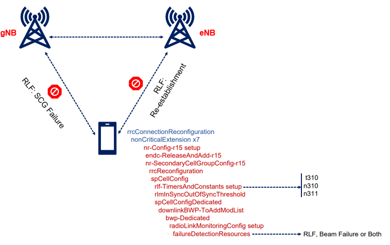

The Radio Link Monitor configuration indicates whether the UE should be monitoring based on the SSB-RS or CSI-RS. In addition, the failureDedectionResources parameter also includes a “purpose” parameter, which can indicate: RLF, Beam Failure or both. There can be multiple instances of the failureDedectionResources parameter.


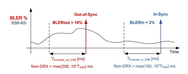
Out-of-Sync and In-Sync
Determination of Out-of-Sync and In-Sync is shown in following figure. The measurements of the RS (Reference Signal) BLER can be configured for the SSB-RS or CSI-RS. Following example shows SSB based monitoring. Here, the measurement evaluation time will also vary depending on whether DRX is configured or not, as well as the Frequency Range (FR1 or FR2).

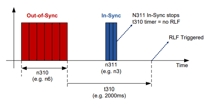
Upon receiving n310 consecutive “out-of-sync” indications for the PSCell (NR cell) from lower layers the UE starts timer t310. Assuming the UE receives n311 In-Sync indication prior to the timer expiring, the t310 timer will stop. If not, the timer expires and the UE triggers a RLF.

Related Posts:
- 5G NR RRC Timers, Counter and Constants
- 5G NR Signaling Radio Bearers (SRBs)
- 5G NR Cell Access Control
- 5G NR RRM Measurement Requirements
- 5G NR Measurement – Serving Cell and Neighbor Cell