

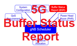
The Buffer Status reporting (BSR) is a MAC layer procedure which is used by the UE to provide information about the amount of data available for transmission in the UL buffers to the serving gNB. In simple words, we can say that, BSR is a MAC layer message from UE to gNB informing that I have something to transmit, can you please give me a Grant to send this data?. Then gNB would allocate the bare minimum amount of UL Grant i.e. PUSCH resource in terms of RBs, if the resource is available.

Using BSR mechansim the gNB MAC schedular can optimize Uplink resources allocation using following.
- When UE has something to transmit then only allocate UL resources (UL Grant)
- Allocate only required RBs (asked by UE) and avoid over allocating of UL resources which save on waste of resources
BSR Pointers
-
- Buffer Status Report is a MAC Layer Feature and specified with 3GPP specification TS 38.321
- BSR is a MAC layer Control Element (MAC-CE)
- gNB configures BSR paraemetes to UE using BSR-Config using RRC signalling
- Three type BSR defined – Regular BSR, Periodic BSR and Padding BSR
- Four formats are specified – Short BSR, Short Truncated BSR, Long BSR and Long Truncated BSR
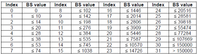
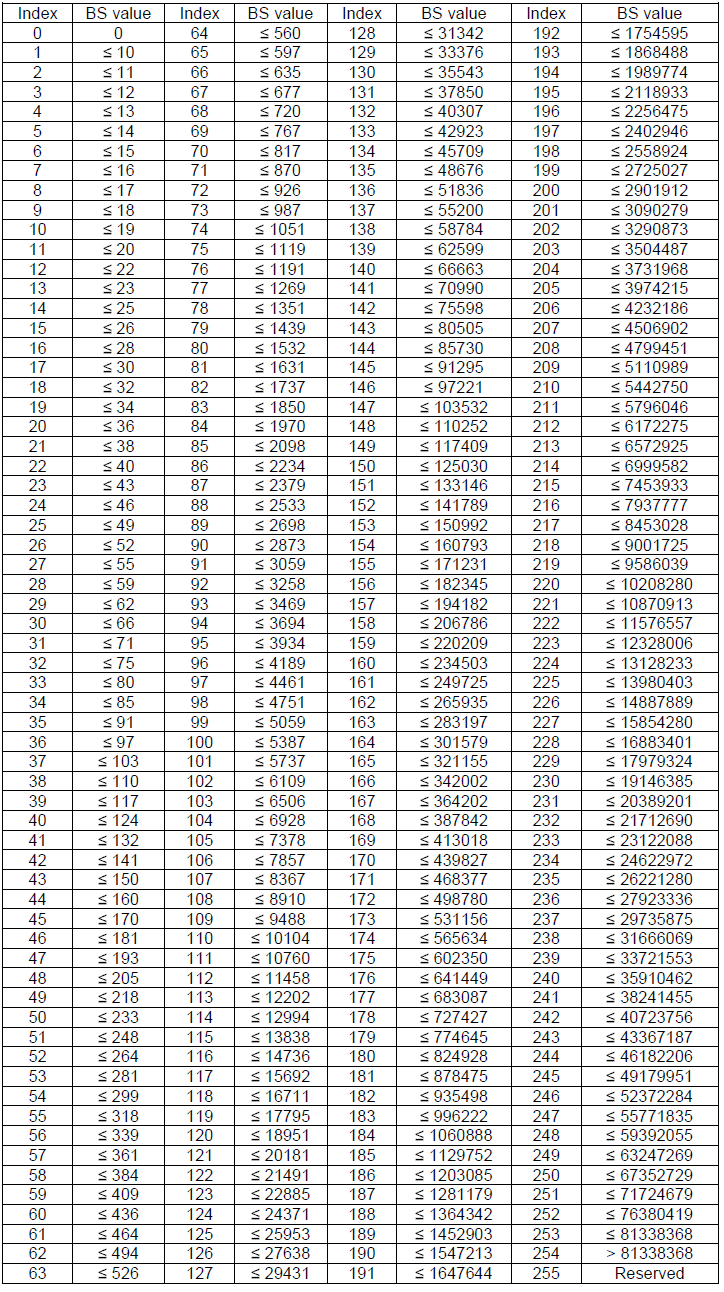
- Short BSR is a 5 bit Buffer Status Reporting mechanism which can accomodate upto 150000 Bytes BSR
- Long BSR is a 8 bit Buffer Status Reporting mechanism which can accomadte upto 150000 Bytes BSR
- LCID=61 is used to identify a Short BSR, whereas an LCID=59 is used to identify a Short Truncated BSR
- LCID=62 is used to identify a Long BSR, whereas an LCID=60 is used to identify a Long Truncated BSR
What Triggers Buffer Status Report (BSR)?
RRC controls Buffer Status Reporting and triggers a BSR MAC-CE (Control Element) if any of the following events occur:
- Regular BSR
- Uplink Data – when resources are allocated, however either no data is available for that LCG (Logical Channel Group) or the data belongs to a logical channel with higher priority.
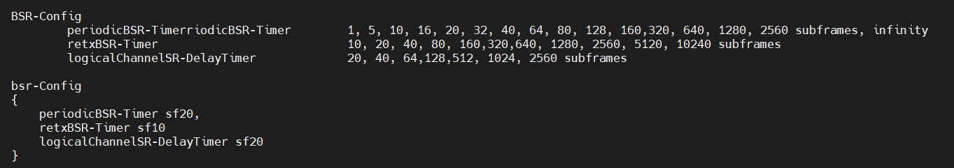
- retxBSR-Timer – when this timer expires and the device has data available for transmission (related to logical channels which belong to a LCG)
- Periodic BSR
- When periodicBSR-Timer expires the BSR is sent. This timer is restarted at UE after each BSR transmission unless ‘truncated’ reports are used. The max value of periodicBST-Timer is ‘infinity’ which means it can be disabled and used as an option for optimization
- Padding BSR– UL resources are allocated and number of padding bits is equal to or larger than the size of the Buffer Status Report. In this case, a BSR is included within the uplink packet to reduce the quantity of padding, i.e. taking advantage of the unused uplink capacity MAC control element (MAC-CE) plus its subheader.
Buffer Status Report (BSR) Types Definition
BSR (Buffer Status Report) consist of either:
- Short BSR : Short BSR includes one LCG ID field and corresponding Buffer Size field. Other LCG buffers are empty.
- Short Truncated BSR : It includes one LCG ID field and corresponding Buffer Size field. Other LCG buffers have data.
- Truncated BSR format : It includes one LCG ID field and corresponding Buffer Size field. Other LCG buffers may have data.
- Long BSR format : It includes all four Buffer Size fields, corresponding to LCG IDs (up to 8 supported).
How to selection a BSR Format
5G specifications have been defined above four formats for BSR and following describes the selection between these four formats.
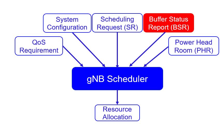
- If the BSR is triggered using either the Regular or Periodic mechanisms then either a Long or Short BSR is generated.
- Long BSR is designed to accommodate information regarding multiple LCG so this format is generated if more than a single LCG has uplink data to transfer.
- Otherwise, a Short BSR is generated to provide information regarding a single LCG
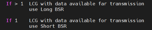

- If the BSR is triggered using the Padding mechanism then the BSR format depends upon the quantity of padding which is available to accommodate the BSR. It is assumed that the quantity of padding is always at least as large as a Short BSR otherwise the Padding BSR would not have been triggered.
- If there is sufficient padding to accommodate a Long BSR then a Long BSR is generated
- Otherwise, if only a single LCG has data to transfer then a Short BSR is generated
- Otherwise, if multiple LCG have data to transfer but the size of the padding can only accommodate a Short BSR then Short Truncated BSR is generated for the LCG with the highest priority Logical Channel.
- Otherwise, a Long Truncated BSR is generated for the LCG with the highest priority Logical Channels

BSR MAC Configuration
Buffer Status Reports are sent per ‘Logical Channel Group‘ (LCG) rather than per ‘Logical Channel‘ although it is possible for an LCG to include only a single Logical Channel. In general, Logical Channels with similar priority are linked to the same LCG. This allows the gNB to differentiate between the volume of highh priority data and the volume of lower priority data.
E.g. Logical Channels used for signalling may be linked to a 1st LCG, while Logical Channels transferring Voice data could be linked to a 2nd LCG, and Logical Channels transferring web-browsing data could be linked to a 3rd LCG. A UE can be configured with up to 8 LCG so the gNB has enough fllexibility when grouping the set of Logical Channels. A Logical Channel is linked to an LCG using the logicalChannelGroup IE within mac-LogicalChannelConfig.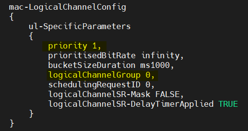
BSR MAC-CE Structure


The structure of a Short BSR and a Short Truncated BSR is shown below and it is consist of 8 bits, where 3 bits used for LCG ID and 5 bits for buffer stauts report.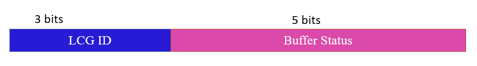


The structure and size of a Short and Short Truncated BSR are the same. The difference between Short BSR and Short Truncated that Short BSR provides information when only a single LCG has data to transfer, whereas the Short Truncated LCG provides information regarding the LCG which includes the highest priority Logical Channel when multiple LCG have data to transfer.
The structure of a Long BSR and a Long Truncated BSR is illustrated in following figure. These MAC CE have the same format but with a variable size. The First Byte represent the LCG ID and other part represent the Buffer Status Reports. The Long BSR and Long Truncated BSR use 8 bits to allows 2^8 = 256 indexes to which can accomodate a larger buffer status of 81338368 Bytes.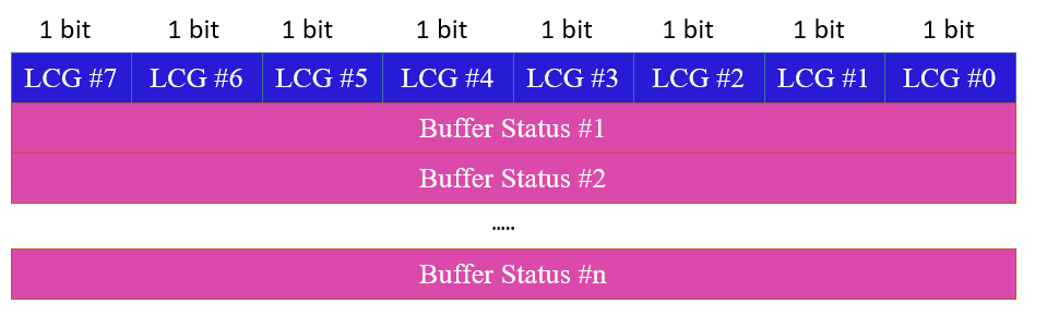


Reference
- 3GPP TS 38.321 5G; NR; Medium Access Control (MAC) protocol specification
Related Posts
- 5G NR PRACH Power Control: MSG1 Tx Power – Open Loop Power
- 5G NR Msg2 Random Access Response (RAR)
- 5G NR Timing Advance: RAR TA and MAC-CE TA
- 5G NR Beam Failure Recovery – BFR