5G SA Handover – Inter gNB-DU and Intra gNB-CU Handover
5G Handover
Mobility (Handover) in an important feature in any telecom generation and so it is in 5G. The basic handover procedure remains same as it was in legacy networks, i.e. UE reports measurement report with neighbor cell PCI and signal strength to source cell, source cell take the decision to start handover procedure to best target cell and Target Cell completes the Handover procedure.
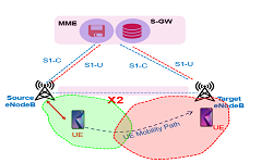
In LTE, we use to have different types of Intra System (LTE to LTE) handover like X2 Based Handover, S1 Based Handover, Inter Frequency, Intra Frequency and Inter sector handovers, similarly 3GPP specification has defined different Intra system (5G NR to 5G NR) handovers, e.g. Xn based Handover, N2 or NGAP Based Handover, Intra and Inter Frequency Handovers.
Apart from above mentioned handovers, 5G has defined some handover types based on newly introduced disaggregated gNB-DU and gNB-CU architecture. Considering gNB-DU and gNB-CU implementation we can have following types of handovers.
- Intra gNB-DU Handover
- Inter gNB-DU and Intra gNB-CU Handover (Source and Target gNB-DU connected to Common gNB-CU)
- Inter gNB-CU Handover (It can be Xn or N2 based Handover)
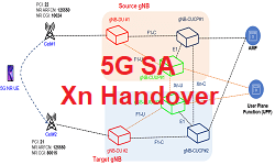
In this post we will discuss about Inter 5G gNB-DU and Intra gNB-CU Handover, When the UE moves from one gNB-DU to another gNB-DU within the same gNB-CU during NR operation.
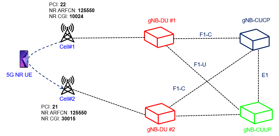
Above picture depicts the mobility scenarios where UEs is connected to source cell#1 with PCI: 22 with gNB-DU#1 and it is moving toward target cell#2 with PCI:21 with gNB-DU#2. In this handover procedure the signaling will involve messaging over F1 interface using F1AP protocols and over E1 interface using E1AP protocols. There will not be any signaling exchange towards 5G Core as all Control Plane and User Plane Context is managed by CU (CUCP and CUUP) both source and target cell comes under same CU.
Handover Call Flow
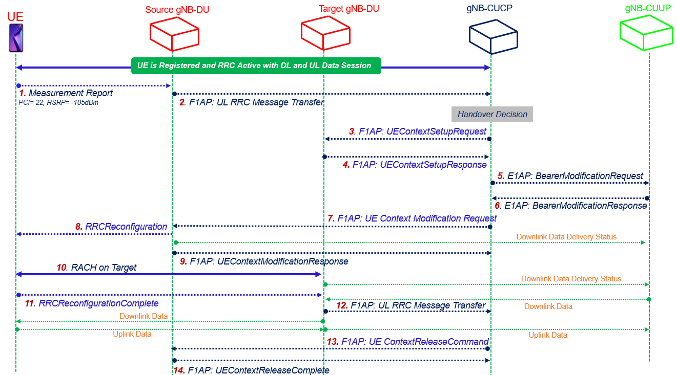
- Step#1 MeasurementReport: The UE sends a MeasurementReport message to the source gNB-DU including the serving cell and neighboring cell signal strength
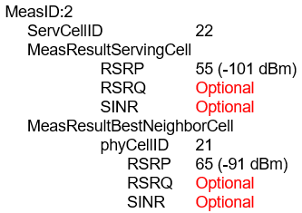
- Step#2 ULRRCMessageTransfer: The source gNB-DU sends an UL RRC MESSAGE TRANSFER message to the gNB-CUCP to convey MeasurementReport information. Based on measurement report CUCP decides for handover.
![]()
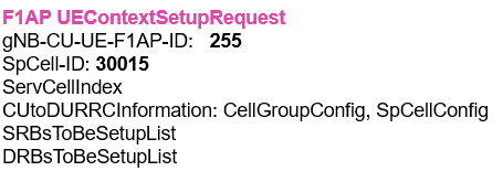
- Step#3 UEContextSetupRequest: Then gNB-CUCP sends an UE CONTEXT SETUP REQUEST message to the target gNB-DU to create an UE context and setup SRBs and DRBs bearers
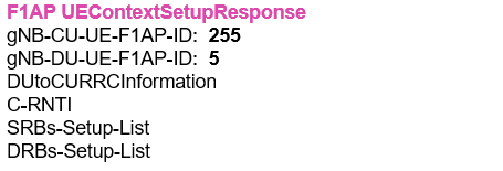
- Step#4 UEConextSetupResponse: The target gNB-DU responds to the gNB-CUCP with an UE CONTEXT SETUP RESPONSE message which new allocated C-RNTI and SRBs and DRBs Setup list
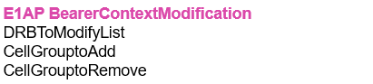
- Step#5-6 BearerModification: gNB-CUCP send BEARER CONTEXT MODIFICATION REQUEST to gNB-CUUP with list of DRBs to be modify and gNB-CUUP respond back with MODIFICATION RESPONSE.
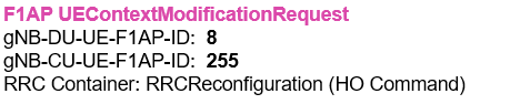
- Step#7 UEContextModificationRequest: The gNB-CUCP sends a UE CONTEXT MODIFICATION REQUEST message to the source gNB-DU, which includes a generated RRCReconfiguration message and indicates to stop the data transmission for the UE. The source gNB-DU also sends a Downlink Data Delivery Status frame to inform the gNB-CUUP about the unsuccessfully transmitted downlink data to the UE.
- Step#8 Handover Command: The source gNB-DU forwards the received RRCReconfiguration message having HO Command to the UE.
- Step#9 UEContextModificationResponse: The source gNB-DU responds to the gNB-CUCP with the UE CONTEXT MODIFICATION RESPONSE message indication that RRCReconfiguration has been sent to UE.

- Step#10 RACH on Target: A Random Access procedure is performed at the target gNB-DU. The target gNB-DU sends a Downlink Data Delivery Status frame to inform the gNB-CU. Downlink packets, which may include PDCP PDUs not successfully transmitted in the source gNB-DU, are sent from the gNB-CU to the target gNB-DU. NOTE: It is up to gNB-CU implementation whether to start sending DL User Data to gNB-DU before or after reception of the Downlink Data Delivery Status.
- Step#11 ReconfigurationComplete: The UE responds to the target gNB-DU with an RRCReconfigurationComplete message.
- Step#12 ULRRCMessageTransfer: The target gNB-DU sends an UL RRC MESSAGE TRANSFER message to the gNB-CU to convey the received RRCReconfigurationComplete message. Downlink packets are sent to the UE. Also, uplink packets are sent from the UE, which are forwarded to the gNB-CU through the target gNB-DU.
![]()
- Step#13 UEContextRelease: The gNB-CUCP sends an UE CONTEXT RELEASE COMMAND message to the source gNB-DU with proper cause value to release the UE context

- Step#14: The source gNB-DU releases the UE context and responds the gNB-CUCP with an UE CONTEXT RELEASE COMPLETE message.

References:
- 3GPP TS 38.401 5G; NG-RAN; Architecture Description
- A Look into 5G Virtual/Open RAN – Part 5: Inter-gNB DU Handover
Related Posts:
- 5G Standalone Mode Registration-Attach Call Flow
- 5G RAN and 5GC Network Slice Signaling
- 5G NR HO Setup: Handover Testing in Cabled Setup
- Open Midhaul F1 Interface F1-C and F1-U
- 5G NR Dual Active Protocol Stack (DAPS) Handover